S3 DIGITAL INPUTS 4. SETPOINT PROGRAMMING
4-22
4.4.17
DIGITAL INPUT FUNCTION: GENERAL SWITCH A-D
Û
ÛÛ
Û
ESCAPE
ESCAPEESCAPE
ESCAPE
MESSAGE
MESSAGEMESSAGE
MESSAGE
Ú
ÚÚ
Ú
6:,7&+#1$0(=
*HQHUDO#6Z1$
B1>75*ð!"ð3XQbQSdUbð1\`XQ^e]UbYS
Û
ÛÛ
Û
ESCAPE
ESCAPEESCAPE
ESCAPE
MESSAGE
MESSAGEMESSAGE
MESSAGE
Ú
ÚÚ
Ú
*(1(5$/#6:,7&+#$=
1RUPDOO\#2SHQ
B1>75*ð>_b]Q\\ið?`U^äð>_b]Q\\ið3\_cUT
Û
ÛÛ
Û
ESCAPE
ESCAPEESCAPE
ESCAPE
MESSAGE
MESSAGEMESSAGE
MESSAGE
Ú
ÚÚ
Ú
%/2&.#,1387
)520#67$57=#3#V
B1>75*ð ðãð% ðè ðY^TYSQdUcðVUQdebUðYcðQSdYfUðgXY\Uð]_d_bðYcðcd_``UTðQcðgU\\ðQcðbe^^Y^Wç
CD5@*ð!
Û
ÛÛ
Û
ESCAPE
ESCAPEESCAPE
ESCAPE
MESSAGE
MESSAGEMESSAGE
MESSAGE
Ú
ÚÚ
Ú
*(1(5$/#6:,7&+#$
$/$50=#2II
B1>75*ð?VVäð<QdSXUTäðE^\QdSXUT
Û
ÛÛ
Û
ESCAPE
ESCAPEESCAPE
ESCAPE
MESSAGE
MESSAGEMESSAGE
MESSAGE
Ú
ÚÚ
Ú
$66,*1#$/$50#5(/$<6=
$ODUP
B1>75*ð1\Qb]äð1\Qb]ðêð1ehY\YQbi"äð1\Qb]ðêð1eh"ðêð1eh#äð1\Qb]ðêð1ehY\YQbi#äð1ehY\YQbi"äð
ðð1eh"ðêð1eh#äð1ehY\YQbi#
Û
ÛÛ
Û
ESCAPE
ESCAPEESCAPE
ESCAPE
MESSAGE
MESSAGEMESSAGE
MESSAGE
Ú
ÚÚ
Ú
*(1(5$/#6:,7&+#$
$/$50#'(/$<=#813#V
B1>75*ð â!ðãð% â
CD5@*ð â!
Û
ÛÛ
Û
ESCAPE
ESCAPEESCAPE
ESCAPE
MESSAGE
MESSAGEMESSAGE
MESSAGE
×
××
×
*(1(5$/#6:,7&+#$
(9(176=#2II
B1>75*ð?^äð?VV
Û
ÛÛ
Û
ESCAPE
ESCAPEESCAPE
ESCAPE
MESSAGE
MESSAGEMESSAGE
MESSAGE
Ú
ÚÚ
Ú
*(1(5$/#6:,7&+#$
75,3=#2II
B1>75*ð?VVäð<QdSXUTäðE^\QdSXUT
Û
ÛÛ
Û
ESCAPE
ESCAPEESCAPE
ESCAPE
MESSAGE
MESSAGEMESSAGE
MESSAGE
Ú
ÚÚ
Ú
$66,*1#75,3#5(/$<6=
7ULS
B1>75*ðDbY`äðDbY`ðêð1ehY\YQbið"äðDbY`ðêð1eh"ðêð1eh#äðDbY`ðêð1ehY\YQbi#
Û
ÛÛ
Û
ESCAPE
ESCAPEESCAPE
ESCAPE
MESSAGE
MESSAGEMESSAGE
MESSAGE
×
××
×
*(1(5$/#6:,7&+#$
75,3#'(/$<=#813#V
B1>75*ð â!ðãð% â
CD5@*ð â!
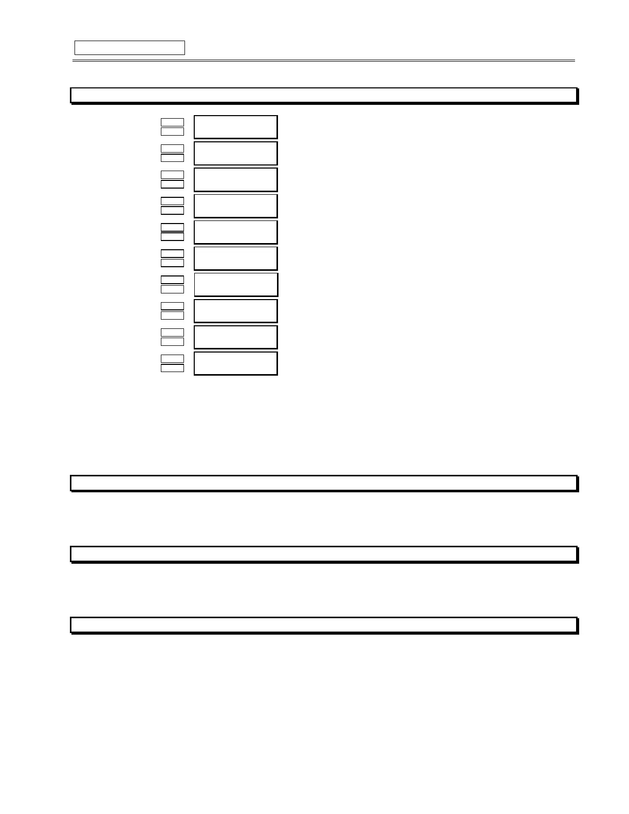
FUNCTION:
There are four General Switch functions that may be assigned to any of the four assignable digital inputs. Once a General Switch func-
tion is chosen for one of the assignable digital inputs, the setpoint messages shown here will follow the assignment message. An alarm
and/or trip may then be configured for that input. The alarm and/or trip may be assigned a common name and a common block time
from motor start if required (if the alarm is to be disabled until some period of time after he motor has been started). A value of zero for
the Block time indicates that the feature is always active, when the motor is stopped or running. The switch may also be defined as nor-
mally open or normally closed. After the block delay has expired, the digital input will be monitored. If the switch is not in its normal state
after the specified delay, an alarm or trip will occur.
4.4.18 DIGITAL INPUT FUNCTION: CAPTURE TRACE
FUNCTION:
This setting allows the user to capture a trace upon command via a switch input. The captured waveforms can then be displayed via the
469PC program.
4.4.19 DIGITAL INPUT FUNCTION: SIMULATE PRE-FAULT
FUNCTION:
This setting allows the user to start Simulate Pre-Fault mode as programmed in S13 via a switch input. This is typically used for relay or
system testing.
4.4.20 DIGITAL INPUT FUNCTION:
SIMULATE FAULT
FUNCTION:
This setting allows the user to start Simulate Fault mode as programmed in S13 via a switch input. This is typically used for relay or
system testing.