S2 SYSTEM SETUP 4. SETPOINT PROGRAMMING
4-12
4.3.2
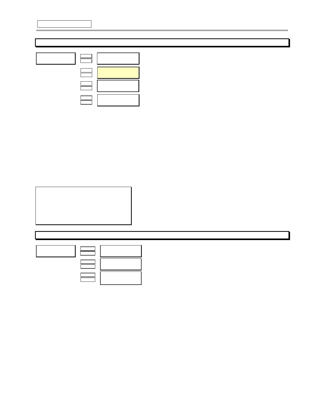
VOLTAGE SENSING
y
#92/7$*(#6(16,1*
y
#>(17(5@#IRU#PRUH
Õ
ÕÕ
Õ
ENTER
ENTERENTER
ENTER
ESCAPE
ESCAPEESCAPE
ESCAPE
Ö
ÖÖ
Ö 97#&211(&7,21#7<3(=
1RQH
B1>75*ð?`U^ð4U\dQäðGiUäðð>_^U
Û
ÛÛ
Û
ESCAPE
ESCAPEESCAPE
ESCAPE
MESSAGE
MESSAGEMESSAGE
MESSAGE
×
××
×
(1$%/(#6,1*/(#97
23(5$7,21=#2))
B1>75*ð1>äð2>äð3>äð?66ðð_bðð12äð32äð?66
>?D5*ðDXYcð]UccQWUðgY\\ð_^\iðRUðcUU^ðYVðFDð3_^^USdY_^ðDi`UðYcðGiUð_bð?`U^ð4U\dQâ
Û
ÛÛ
Û
ESCAPE
ESCAPEESCAPE
ESCAPE
MESSAGE
MESSAGEMESSAGE
MESSAGE
Ú
ÚÚ
Ú
92/7$*(#75$16)250(5
5$7,2=#68133=4
B1>75*ð!â *!ðãð# â *!
CD5@*ð â !
Û
ÛÛ
Û
ESCAPE
ESCAPEESCAPE
ESCAPE
MESSAGE
MESSAGEMESSAGE
MESSAGE
×
××
×
02725#1$0(3/$7(
92/7$*(=#73339
B1>75*ð! ðãð"
CD5@*ð!
FUNCTION:
The manner in which the voltage transformers are connected must be entered here. A value of ''None', indicates that no voltage meas-
urement is required.
Note that phase reversal is disabled for single VT operation. All voltages are assumed balanced. Also, frequency is only available for AN
or AB connections.
If voltage measurements are to be made, the turns ratio of the voltage transformers must be entered. The VT ratio must be chosen
such that the secondary voltage of the VTs is between 40 and 240 V when the primary is at Motor Nameplate Voltage.
All voltage protection features that require a level setpoint are programmed as a percent of the Motor Nameplate Voltage or rated volt-
age. Where Motor Nameplate Voltage represents the rated design voltage line to line.
EXAMPLE:
c
Motor Nameplate Voltage is 4160 V
VTs are 4160/120 Open Delta
Set: VT Connection Type: Open Delta
VT Ratio: 34.67:1
Motor Nameplate Voltage: 4160
4.3.3
POWER SYSTEM
y
#32:(5#6<67(0
y
#>(17(5@#IRU#PRUH
Õ
ÕÕ
Õ
ENTER
ENTERENTER
ENTER
ESCAPE
ESCAPEESCAPE
ESCAPE
Ö
ÖÖ
Ö 120,1$/# 6<67(0
)5(48(1&<=##93#+]
B1>75*ð% ð8jäð& ð8jäðFQbYQR\U
Û
ÛÛ
Û
ESCAPE
ESCAPEESCAPE
ESCAPE
MESSAGE
MESSAGEMESSAGE
MESSAGE
×
××
×
6<67(0#3+$6(
6(48(1&(=##$%&
B1>75*ð123äð132
Û
ESCAPE
MESSAGE
×
63(('5#3+$6(
6(48(1&(=##$%&
B1>75*ð123äð132
>?D5*ðdXYcð]UccQWUðcUU^ð_^\iðYVðdXUð"ãC`UUTð]_d_bð`b_dUSdY_^ðYcðU^QR\UT
FUNCTION:
The nominal system frequency must be entered here. This setpoint allows the SR469 to determine the internal sampling rate for maxi-
mum accuracy.
The SR469 may be used on variable frequency drives when the Nominal System Frequency is chosen as Variable. All of the elements
function in the same manner with the following exceptions: the ratio of negative to positive sequence current is calculated from 0–30%,
not 40%, and the voltage and power elements will work properly if the voltage waveform is approximately sinusoidal. An unfiltered volt-
age waveform from a pulse width modulated drive cannot be measured accurately; however, the current waveform is approximately
sinusoidal and can be measured accurately. All current elements will function properly. Note, however, that undervoltage and underfre-
quency elements will not work as instantaneous using variable frequency. If variable is chosen, the filtering algorithm will increase trip
and alarm times by up to a maximum of 270ms when the level is close to the threshold. If the level exceeds the threshold by a signifi-
cant amount, trip and alarm times will decrease until they match the programmed delay. The exceptions to this increased time are the
short circuit, ground fault, and differential elements which will trip as per specification.
If the sequence of phase rotation for a given plant is ACB rather than the standard ABC, the System Phase Sequence setpoint may be
used to accommodate this. This setpoint allows the SR469 to properly calculate Phase Reversal, Negative Sequence, and power quan-
tities. The Speed2 Phase Sequence can be programmed to accommodate the reversed motor rotation at Speed2.