4. SETPOINT PROGRAMMING S4 OUTPUT RELAYS
4-23
4.4.21 DIGITAL INPUT FUNCTION: SIMULATE PRE-FAULT…FAULT
FUNCTION:
This setting allows the user to start Simulate Pre-Fault to Fault mode as programmed in S13 via a switch input. This is typically used for
relay or system testing.
4.5 S4 OUTPUT RELAYS
Five of the six output relays are always non-failsafe, R6 Service is always failsafe. As failsafe, R6 relay will be energized normally and
de-energize when called upon to operate. It will also de-energize when control power to the SR469 is lost and therefore, be in its oper-
ated state. All other relays, being non-failsafe, will be de-energized normally and energize when called upon to operate. Obviously, when
control power is lost to the SR469, the output relays must be de-energized and therefore, they will be in their non-operated state.
Shorting bars in the drawout case ensure that when the SR469 is drawn out, no trip or alarm occurs. The R6 Service output will however
indicate that the SR469 has been drawn out.
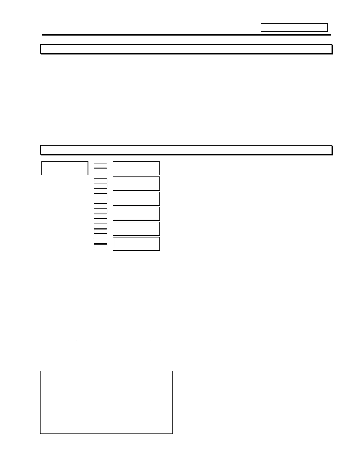
4.5.1
RELAY RESET MODE
y
5(/$<#5(6(7#02'(
y
>(17(5@#IRU#PRUH
Õ
ÕÕ
Õ
ENTER
ENTERENTER
ENTER
ESCAPE
ESCAPEESCAPE
ESCAPE
Ö
ÖÖ
Ö 54#75,3=
$OO#5HVHWV
B1>75*ð1\\ðBUcUdcäðBU]_dUðBUcUdð?^\iäð;Ui`QTðBUcUdð?^\i
Û
ÛÛ
Û
ESCAPE
ESCAPEESCAPE
ESCAPE
MESSAGE
MESSAGEMESSAGE
MESSAGE
Ú
ÚÚ
Ú
55#$8;,/,$5<=
$OO#5HVHWV
B1>75*ð1\\ðBUcUdcäðBU]_dUðBUcUdð?^\iäð;Ui`QTðBUcUdð?^\i
Û
ÛÛ
Û
ESCAPE
ESCAPEESCAPE
ESCAPE
MESSAGE
MESSAGEMESSAGE
MESSAGE
Ú
ÚÚ
Ú
56#$8;,/,$5<=
$OO#5HVHWV
B1>75*ð1\\ðBUcUdcäðBU]_dUðBUcUdð?^\iäð;Ui`QTðBUcUdð?^\i
Û
ÛÛ
Û
ESCAPE
ESCAPEESCAPE
ESCAPE
MESSAGE
MESSAGEMESSAGE
MESSAGE
Ú
ÚÚ
Ú
57#$/$50=
$OO#5HVHWV
B1>75*ð1\\ðBUcUdcäðBU]_dUðBUcUdð?^\iäð;Ui`QTðBUcUdð?^\i
Û
ÛÛ
Û
ESCAPE
ESCAPEESCAPE
ESCAPE
MESSAGE
MESSAGEMESSAGE
MESSAGE
Ú
ÚÚ
Ú
58#%/2&.#67$57
$XWR05HVHW
B1>75*ð>á1
Û
ÛÛ
Û
ESCAPE
ESCAPEESCAPE
ESCAPE
MESSAGE
MESSAGEMESSAGE
MESSAGE
×
××
×
59#6(59,&(=
$OO#5HVHWV
B1>75*ð1\\ðBUcUdcäðBU]_dUðBUcUdð?^\iäð;Ui`QTðBUcUdð?^\i
FUNCTION:
RESETTING THE SR469
A latched trip or alarm may be reset at any time, providing that the condition that caused the trip or alarm is no longer present. Unlatched
trips and alarms will reset automatically once the condition is no longer present. If any condition may be reset, the Reset Possible LED
will be lit. All Block Start features will reset automatically when the lockout time has expired and the trip has been reset.
The other relays may be programmed to All Resets which allows reset from the front keypad or the remote reset switch input or the
communications port. Optionally, relays 1,2,3,4,6 may be programmed to reset by the Remote Reset Only (by the remote reset switch
input or the communications port) or Keypad Reset Only (reset only by relay keypad).
WARNING
:NO
trip or alarm element must EVER be assigned to two output relays where one is Remote Reset Only and the other is
Keypad Reset Only. The trip or alarm will be unresettable if this occurs.
EXAMPLE:
Serious trips such as Short Circuit and Ground Fault may be
assigned to R2 so that they may only be reset via. the Re-
mote Reset terminals (D18 and D23) or the Communication
Port. The Remote Reset terminals would be connected to a
keyswitch so that only authorized personnel could reset
such a critical trip.
• Assign only Short Circuit and Ground Fault to R2
• Program R2 to Remote Reset Only