2. INSTALLATION ELECTRICAL
2-17
2.2.12 DRAWOUT INDICATOR
The Drawout Indicator is simply a jumper from E12 to F12 on the SR469 unit. When the SR469 is withdrawn from the case, terminals
E12 and F12 will be open. This may be useful for differentiating between loss of control power as indicated by the R6 SERVICE relay
and withdrawal of the unit.
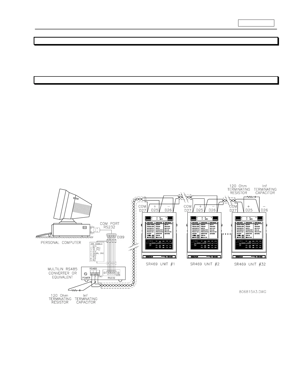
2.2.13
RS485 COMMUNICATIONS PORTS
Two totally independent two-wire RS485 ports are provided. Up to 32 SR469's can be daisy-chained together on a communication channel
without exceeding the driver capability. For larger systems, additional serial channels must be added. It is also possible to use commercially
available repeaters to increase the number of relays on a single channel to more than 32. Suitable cable should have a characteristic
impedance of 120 ohms (eg. Belden #9841) and total wire length should not exceed 4000 ft. Commercially available repeaters will allow for
transmission distances greater than 4000 ft.
Voltage differences between remote ends of the communication link are not uncommon. For this reason, surge protection devices are
internally installed across all RS485 terminals. Internally, an isolated power supply with an optocoupled data interface is used to prevent
noise coupling.
To ensure that all devices in a daisy-chain are at the same potential, it is imperative that the common terminals of
each RS485 port are tied together and grounded only once, at the master. Failure to do so may result in intermittent or failed
communications.
The source computer/PLC/SCADA system should have similar transient protection devices installed, either internally or
externally, to ensure maximum reliability. Ground the shield at one point only, as shown in Figure 2-26, to avoid ground loops.
Correct polarity is also essential. SR469's must be wired with all ‘+’ terminals connected together, and all ‘–’ terminals connected together.
Each relay must be daisy-chained to the next one. Avoid star or stub connected configurations. The last device at each end of the daisy
chain should be terminated with a 120 ohm 1/4 watt resistor in series with a 1nF capacitor across the ‘+’ and ‘–’ terminals. Observing these
guidelines will result in a reliable communication system that is immune to system transients.
Figure 2-26 RS485 COMMUNICATIONS INTERFACE