4. SETPOINT PROGRAMMING S3 DIGITAL INPUTS
4-21
4.4.16
DIGITAL INPUT FUNCTION: TACHOMETER
Û
ÛÛ
Û
ESCAPE
ESCAPEESCAPE
ESCAPE
MESSAGE
MESSAGEMESSAGE
MESSAGE
Ú
ÚÚ
Ú
5$7('#63(('=
6933#530
B1>75*ð! ã'"
CD5@*!
Û
ÛÛ
Û
ESCAPE
ESCAPEESCAPE
ESCAPE
MESSAGE
MESSAGEMESSAGE
MESSAGE
Ú
ÚÚ
Ú
7$&+20(7(5
$/$50=#2II
B1>75*ð?VVäð<QdSXUTäðE^\QdSXUT
Û
ÛÛ
Û
ESCAPE
ESCAPEESCAPE
ESCAPE
MESSAGE
MESSAGEMESSAGE
MESSAGE
Ú
ÚÚ
Ú
$66,*1#$/$50#5(/$<6=
$ODUP
B1>75*ð1\Qb]äð1\Qb]ðêð1ehY\YQbi"äð1\Qb]ðêð1eh"ðêð1eh#äð1\Qb]ðêð1ehY\YQbi#äð1ehY\YQbi"äð
ðð1eh"ðêð1eh#äð1ehY\YQbi#
Û
ÛÛ
Û
ESCAPE
ESCAPEESCAPE
ESCAPE
MESSAGE
MESSAGEMESSAGE
MESSAGE
Ú
ÚÚ
Ú
7$&+20(7(5#$/$50
63(('=#43#(#5DWHG
B1>75*ð%ã!
CD5@*ð!
Û
ÛÛ
Û
ESCAPE
ESCAPEESCAPE
ESCAPE
MESSAGE
MESSAGEMESSAGE
MESSAGE
Ú
ÚÚ
Ú
7$&+20(7(5#$/$50
'(/$<=#4#V
B1>75*ð!ã"%
CD5@*ð!
Û
ÛÛ
Û
ESCAPE
ESCAPEESCAPE
ESCAPE
MESSAGE
MESSAGEMESSAGE
MESSAGE
×
××
×
7$&+20(7(5#$/$50
(9(176=#2II
B1>75*ð?^äð?VV
Û
ÛÛ
Û
ESCAPE
ESCAPEESCAPE
ESCAPE
MESSAGE
MESSAGEMESSAGE
MESSAGE
Ú
ÚÚ
Ú
7$&+20(7(5
75,3=#2II
B1>75*ð?VVäð<QdSXUTäðE^\QdSXUT
Û
ÛÛ
Û
ESCAPE
ESCAPEESCAPE
ESCAPE
MESSAGE
MESSAGEMESSAGE
MESSAGE
Ú
ÚÚ
Ú
$66,*1#75,3#5(/$<6=
7ULS
B1>75*ðDbY`äðDbY`ðêð1ehY\YQbið"äðDbY`ðêð1eh"ðêð1eh#äðDbY`ðêð1ehY\YQbi#
Û
ÛÛ
Û
ESCAPE
ESCAPEESCAPE
ESCAPE
MESSAGE
MESSAGEMESSAGE
MESSAGE
Ú
ÚÚ
Ú
7$&+20(7(5#75,3
63(('=#43#(#5DWHG
B1>75*ð%ã)%
CD5@*ð!
Û
ÛÛ
Û
ESCAPE
ESCAPEESCAPE
ESCAPE
MESSAGE
MESSAGEMESSAGE
MESSAGE
×
××
×
7$&+20(7(5#75,3
'(/$<=#4#V
B1>75*ð!ã"%
CD5@*ð!
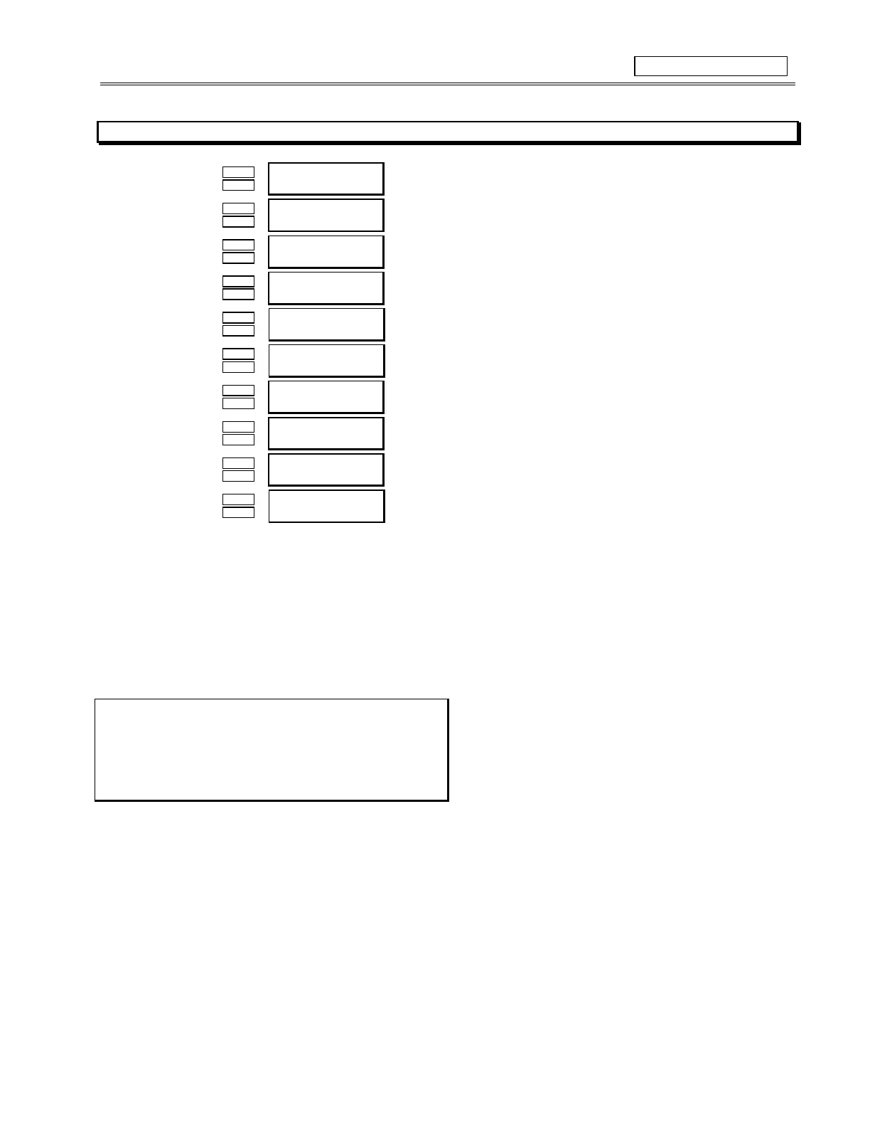
FUNCTION:
Once the TACHOMETER function is chosen for one of the assignable digital inputs, the setpoint messages shown here will follow the
assignment message. The period of time between each switch closure measured and converted to an RPM value based on one closure
per revolution. A trip and alarm may be configured such that the motor or load must be at a certain speed within a set period of time
from the initiation of motor starting. The tachometer trip and alarm are ignored while the motor is stopped. The RPM value may be
viewed in the ‘Speed’ sub-group of Actual Values, Page 2, ‘METERING’
EXAMPLE
:
An inductive proximity probe or hall effect gear tooth sensor may
be used to sense the key on the motor. The probe could be pow-
ered from the +24V from the input switch power supply. The NPN
transistor output could be taken to one of the assignable switch
inputs configured as a tachometer.