S6 CURRENT ELEMENTS 4. SETPOINT PROGRAMMING
4-40
4.7.1
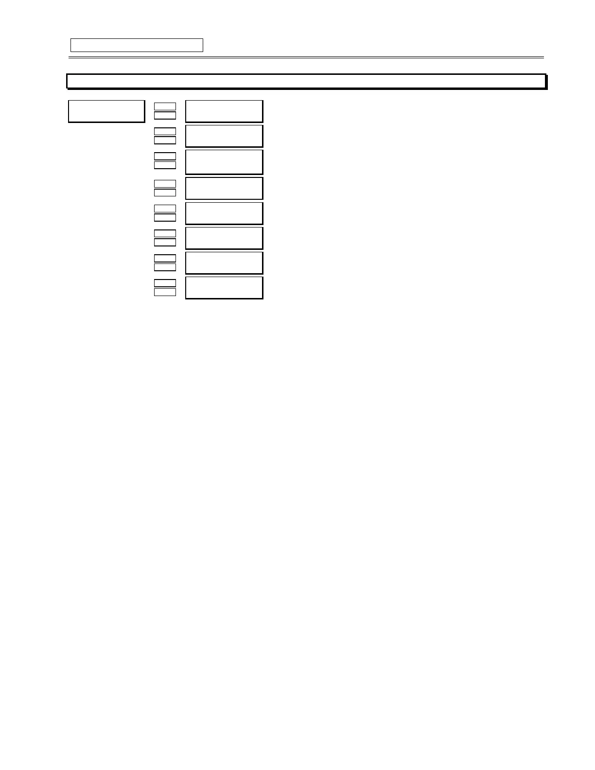
SHORT CIRCUIT
y
#6+257#&,5&8,7#75,3
y
#>(17(5@#IRU#PRUH
Õ
ÕÕ
Õ
ENTER
ENTERENTER
ENTER
ESCAPE
ESCAPEESCAPE
ESCAPE
Ö
ÖÖ
Ö 6+257#&,5&8,7
75,3=#2II
B1>75*ð?VVäð<QdSXUTäðE^\QdSXUT
Û
ÛÛ
Û
ESCAPE
ESCAPEESCAPE
ESCAPE
MESSAGE
MESSAGEMESSAGE
MESSAGE
Ú
ÚÚ
Ú
6+257#&,5&8,7#75,3
29(55($&+#),/7(5=#2II
B1>75*ð?^äð?VV
Û
ÛÛ
Û
ESCAPE
ESCAPEESCAPE
ESCAPE
MESSAGE
MESSAGEMESSAGE
MESSAGE
Ú
ÚÚ
Ú
$66,*1#75,3#5(/$<6=
7ULS
B1>75*ðDbY`äðDbY`ðêð1ehY\YQbið"äðDbY`ðêð1eh"ðêð1eh#äðDbY`ðêð1ehY\YQbi#äð1ehY\YQbið"ä
ð1eh"ðêð1eh#äð1ehY\YQbið#
Û
ÛÛ
Û
ESCAPE
ESCAPEESCAPE
ESCAPE
MESSAGE
MESSAGEMESSAGE
MESSAGE
Ú
ÚÚ
Ú
6+257#&,5&8,7#75,3
3,&.83=#4313#[#&7
B1>75*ð"â ðãð" â
CD5@*ð â!
Û
ÛÛ
Û
ESCAPE
ESCAPEESCAPE
ESCAPE
MESSAGE
MESSAGEMESSAGE
MESSAGE
Ú
ÚÚ
Ú
,17(17,21$/#62K,3
'(/$<#=#3#PV
B1>75*ð ðãð!
CD5@*ð!
Û
ÛÛ
Û
ESCAPE
ESCAPEESCAPE
ESCAPE
MESSAGE
MESSAGEMESSAGE
MESSAGE
Ú
ÚÚ
Ú
6+257#&,5&8,7#75,3
%$&.83=#2II
B1>75*ð?^äð?VV
Û
ÛÛ
Û
ESCAPE
ESCAPEESCAPE
ESCAPE
MESSAGE
MESSAGEMESSAGE
MESSAGE
Ú
ÚÚ
Ú
$66,*1#%$&.83
5(/$<6=#$X[LOLDU\5
B1>75*ð1ehY\YQbi"äð1eh"ðêð1eh#äð1ehY\YQbi#
Û
ÛÛ
Û
ESCAPE
ESCAPEESCAPE
ESCAPE
MESSAGE
MESSAGEMESSAGE
MESSAGE
×
××
×
6+257#&,5&8,7#75,3
%$&.83#'(/$<=#533#PV
B1>75*ð! ðãð"
CD5@*!
FUNCTION:
Note:Care must be taken when turning On this feature. If the interrupting device (contactor or circuit breaker) is not rated to
break the fault current, this feature should be disabled. Alternatively, this feature may be assigned to an auxiliary relay and
connected such that it trips an upstream device that is capable of breaking the fault current.
If turned On, the Short Circuit element will function as follows:
Once the magnitude of any one of either Ia, Ib, or Ic exceeds the Pickup Level × Phase CT Primary for a period of time specified by the
Delay, a Trip will occur. There is also a backup trip feature that can be enabled. The backup delay should be greater than the short cir-
cuit delay plus the breaker clearing time. If the backup is On, and a Short Circuit trip has initiated, if the phase current to the motor per-
sists for a period of time that exceeds the backup delay, a second trip will occur. It is intended that this second trip be assigned to R2 or
R3 which would be dedicated as an upstream breaker trip relay.
Various situations (eg. charging a long line to the motor or power factor correction capacitors) may cause transient inrush currents dur-
ing motor starting that may exceed the Short Circuit Pickup level only for a very short period of time. The Short Circuit time delay is ad-
justable in 10 ms increments. The delay can be fine tuned to an application such that it still responds very fast, but rides through normal
operational disturbances. Normally, the Phase Short Circuit time delay will be set as quick as possible, 0 ms. Time may have to be in-
creased if nuisance tripping occurs.
When a motor starts, the starting current (typically 6 × FLA for an induction motor) has an asymmetrical component. This asymmetrical
current may cause one phase to see as much as 1.6 times the normal RMS starting current. If the short circuit level was set at 1.25
times the symmetrical starting current, it is probable that there would be nuisance trips during motor starting. A rule of thumb has been
developed over time that short circuit protection at least 1.6 times the symmetrical starting current value. This allows the motor to start
without nuisance tripping.
The overreach filter removes the DC component from the asymmetrical current present at the moment a fault occurs. This results in no
overreach whatsoever, however, the response time slows slightly (10-15ms) but times still remain within specifications.