ELECTRICAL 2. INSTALLATION
2-10
2.2.5
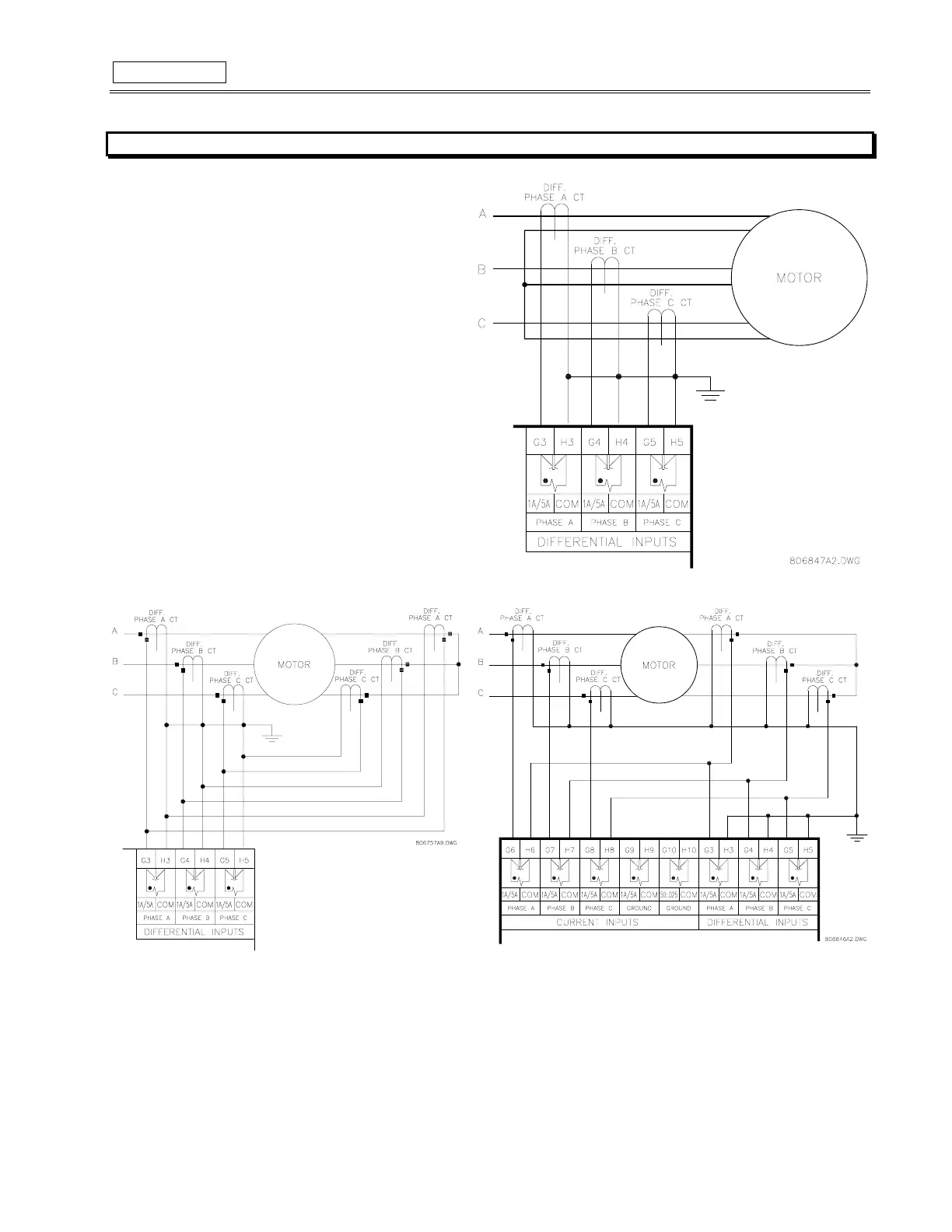
DIFFERENTIAL CURRENT INPUTS
The SR469 has three channels for differential current inputs,
each with an isolating transformer. There are no internal ground
connections on the current inputs. Each differential CT circuit is
shorted by automatic mechanisms on the SR469 case if the unit
is withdrawn. The maximum differential CT primary current is
5000 A.
The SR469 will measure up to 5 A secondary current for the
differential CT inputs. Since the conversion range is relatively
small, the 1A or 5A option is field programmable. Proper
selection of this setpoint will ensure proper reading of primary
phase differential current. The 1A/5A differential CT chosen must
be capable of driving the SR469 differential CT burden (see
Specifications for ratings).
The differential CTs may be core balance as shown in figure
2-16. Alternatively, the summation of two CTs per phase into the
differential input will provide a larger zone of protection. If the
summation of two CTs is used, observation of CT polarity is
important (see Figure 2-17). The summation method may also
be implemented using the phase CTs as in figure 2-18. They will
have to have the same CT ratio.
Figure 2-16 CORE BALANCE METHOD
Figure 2-17 SUMMATION METHOD
Figure 2-18 SUMMATION WITH PHASE CT METHOD