4. SETPOINT PROGRAMMING S5 THERMAL MODEL
4-25
4.6.1
MOTOR THERMAL LIMITS
One of the principle enemies of motor life is heat. When a motor is specified, the purchaser communicates to the manufacturer what the
loading conditions and duty cycle will be, as well as, environment and other pertinent information about the driven load such as starting
torque, etc. The manufacturer then provides a stock motor or builds a motor that should have a reasonable life under those conditions.
Motor thermal limits are dictated by the design of both the stator and the rotor. Motors have three modes of operation: locked rotor or
stall (when the rotor is not turning), acceleration (when the rotor is coming up to speed), and running (when the rotor turns at near syn-
chronous speed). Heating occurs in the motor during each of these conditions in very distinct ways. Typically, during motor starting,
locked rotor and acceleration conditions, the motor is rotor limited. That is to say that the rotor will approach its thermal limit before the
stator. Under locked rotor conditions, voltage is induced in the rotor at line frequency, 50 or 60 Hz. This voltage causes a current to flow
in the rotor, also at line frequency, and the heat generated (I
2
R) is a function of the effective rotor resistance. At 50 or 60 Hz, the reac-
tance of the rotor cage causes the current to flow at the outer edges of the rotor bars. The effective resistance of the rotor is therefore at
a maximum during a locked rotor condition as is rotor heating. When the motor is running at rated speed, the voltage induced in the rotor
is at a low frequency (approx. 1 Hz) and therefore, the effective resistance of the rotor is reduced quite dramatically. During running
overloads, the motor thermal limit is typically dictated by stator parameters. Some special motors might be all stator or all rotor limited.
During acceleration, the dynamic nature of the motor slip dictates that rotor impedance is also dynamic, and a third overload thermal
limit characteristic is necessary.
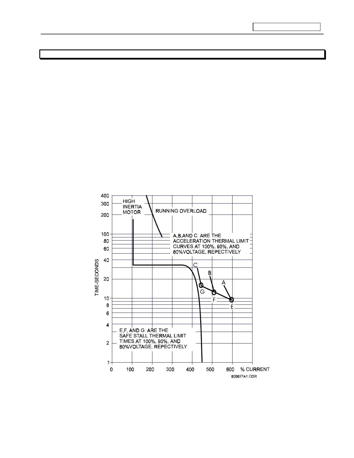
Figure 4-7 illustrates typical thermal limit curves. The motor starting characteristic is shown for a high inertia load @ 80% voltage. If the
motor started quicker, the distinct characteristics of the thermal limit curves would not be required and the running overload curve would
be joined with locked rotor safe stall times to produce a single overload curve.
Figure 4-7 TYPICAL TIME-CURRENT AND THERMAL LIMIT CURVES (ANSI/IEEE C37.96)
The motor manufacturer should provide a safe stall time or thermal limit curves for any motor they sell. To program the SR469 for
maximum protection, it is necessary to ask for these items when the motor is out for bid. These thermal limits are intended to be used as
guidelines and their definition is not always precise. When operation of the motor exceeds the thermal limit, the motor insulation does
not immediately melt. Rather, the rate of insulation degradation has reached a point that motor life will be significantly reduced if it is run
any longer in that condition.