15
S
MARTNA™ 10G NETWORK ACCESS (SMARTNA-X)
SETTING UP SMARTNA-X | POWERING UP THE SYSTEM
DRAFT
Follow these steps to set up the chassis with your TAP modules and install it into a server rack.
1. Unpack all supplied items and lay them on a workbench.
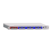
2. Attach the mounting brackets to either side of the SmartNA-X chassis using the screws provided (Figure 3-1).
3. Install the appliance into a standard 19” rack (the appliance will occupy 1 rack unit).
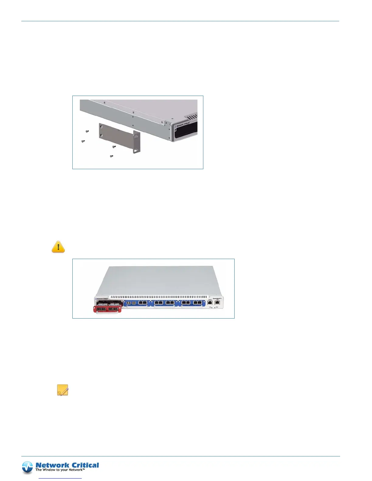
4. Insert SmartNA-X TAP modules in the chassis slots as follows:
• Red module (max 10 Gbit/s) – insert in left-hand side slot only (as shown in Figure 3-2)
• Blue module (max 1 Gbit/s) – insert in any slot (including left-hand slot if desired)
CAUTION: Blanking plates MUST be fitted to unused slots
to ensure correct cooling.
Powering up the system
Depending on your chassis configuration, the unit will be fitted with a single PSU (PSU-1) or dual independent
PSUs (PSU-1 and PSU-2, Figure 3-3).
NOTE
: Dual PSUs should be fed from two truly independent supplies to eliminate single points of failure.
Figure 3-1 Attaching mounting brackets to the chassis
Figure 3-2 Red TAP modules must be inserted in the left-hand slot only, Blue TAP modules can be inserted in any slot.