1.13 EDH0162En1040 – 06/99
MM4005 Introduction
• Do not send REMOTE commands when in an Intermediate Local mode
(for instance when entering the value of a move).
• Do not interfere with a HOME Search cycle, including read commands.
• The preferred remote operation is the REMOTE mode, obtained by
using the appropriate command.
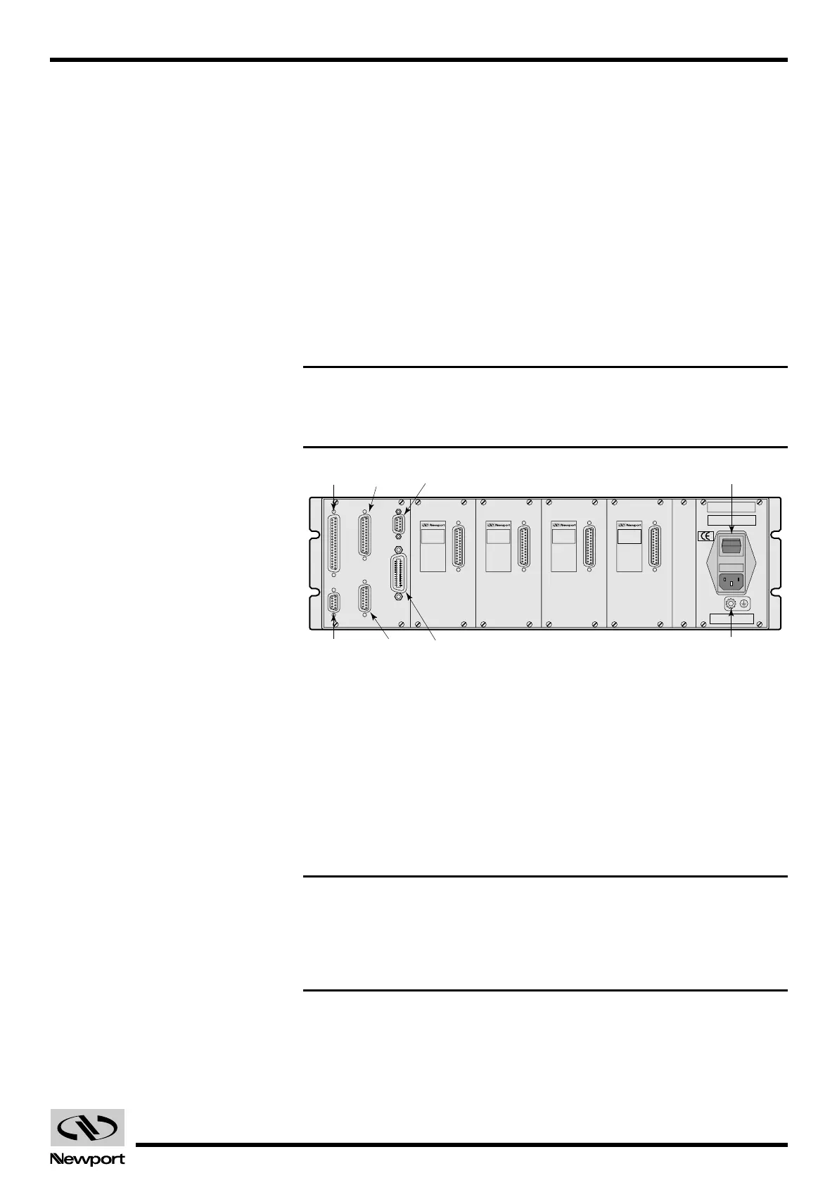
1.3.4 Rear Panel Description
Before attempting to operate the MM4005, it must first be properly con-
nected and configured. Carefully unpack the controller and place it on a flat
surface. Save all packing materials.
Begin by familiarizing yourself with the connectors and controls on the
rear panel (Fig. 1.6).
NOTE
For complete connector description and pin-outs see Appendix B,
Connector Pin-Outs.
Fig. 1.6 — Rear panel of the MM4005.
1.3.4.1 Axis Modules
The MM4005 can accommodate up to four motor driver cards. Each motor
driver card has a 25-pin D-Sub connector, mounted on a small panel visible
from the rear of the controller, for attaching the motion device. Uninstalled
axes have a blank panel with no connector.
Each driver module has an identification label which clearly specifies the
model and the type of motor it is configured to drive.
CAUTION
Carefully read the labels on the driver cards and make sure the specifica-
tions (motor type, voltage, current, etc.) match those for one the motion
devices you intend to connect. Serious damage could occur if a stage is
connected to the wrong driver card.
1.3.4.2 GPIO Connector
This 37-pin D-Sub connector is used for general purpose digital Input/Output
signals. The MM4005 offers two separate 8-bit digital ports, one for input and
one for output. A variety of commands are available for control and interface
using these ports from within a motion program.
Axe 1 Axe 2 Axe 3 Axe 4
GPIO RS-232-C
IEEE-488 Ground Post
Power Switch
Auxiliary
Motor
Interlock
Remote
Control
ATTENTION
Pour une continuité de protection contre les risques de feu, remplacer
uniquement avec des fusibles de type et de caractéristiques spécifiées
Utiliser seulement des fusibles: T6.3A/250V
ENTREE CA (Sélection automatique)
AC INPUT (Automatic selection)
100-127V 3.6A 200-240V 1.8A
50/60Hz 400VA MAX.
WARNING
For continued protection against risk of fire, replace
only with fuse of the specified type and current rating.
Use only fuse: T6.3A/250V
O
I
A
U
X
I
L
I
A
R
Y
R
S
2
3
2
I
E
E
E
4
8
8
G
P
I
O
P
O
W
E
R
/
I
N
H
I
R
E
M
O
T
E
C
O
N
T
R
O
L
CAUTION
Do not connect or
disconnect while
power is applied
DC MOTOR
P/N: E1025A
Option #
(UE17CC)
V = 12V, I = 0.22A
5VDC Encod. supply:
CAUTION
Do not connect or
disconnect while
power is applied
DC MOTOR
P/N: E1025A
Option #
(UE17CC)
V = 12V, I = 0.22A
5VDC Encod. supply:
CAUTION
Do not connect or
disconnect while
power is applied
DC MOTOR
P/N: E1025A
Option #
(UE17CC)
V = 12V, I = 0.22A
5VDC Encod. supply:
CAUTION
Do not connect or
disconnect while
power is applied
DC MOTOR
P/N: E1025A
Option #
(UE17CC)
V = 12V, I = 0.22A
5VDC Encod. supply:
Artisan Technology Group - Quality Instrumentation ... Guaranteed | (888) 88-SOURCE | www.artisantg.com
 Loading...


