4.21 EDH0162En1040 – 06/99
MM4005 Motion Control Tutorial
Encoders
PID closed-loop motion control requires a position sensor. The most widely
used technology by far are incremental encoders.
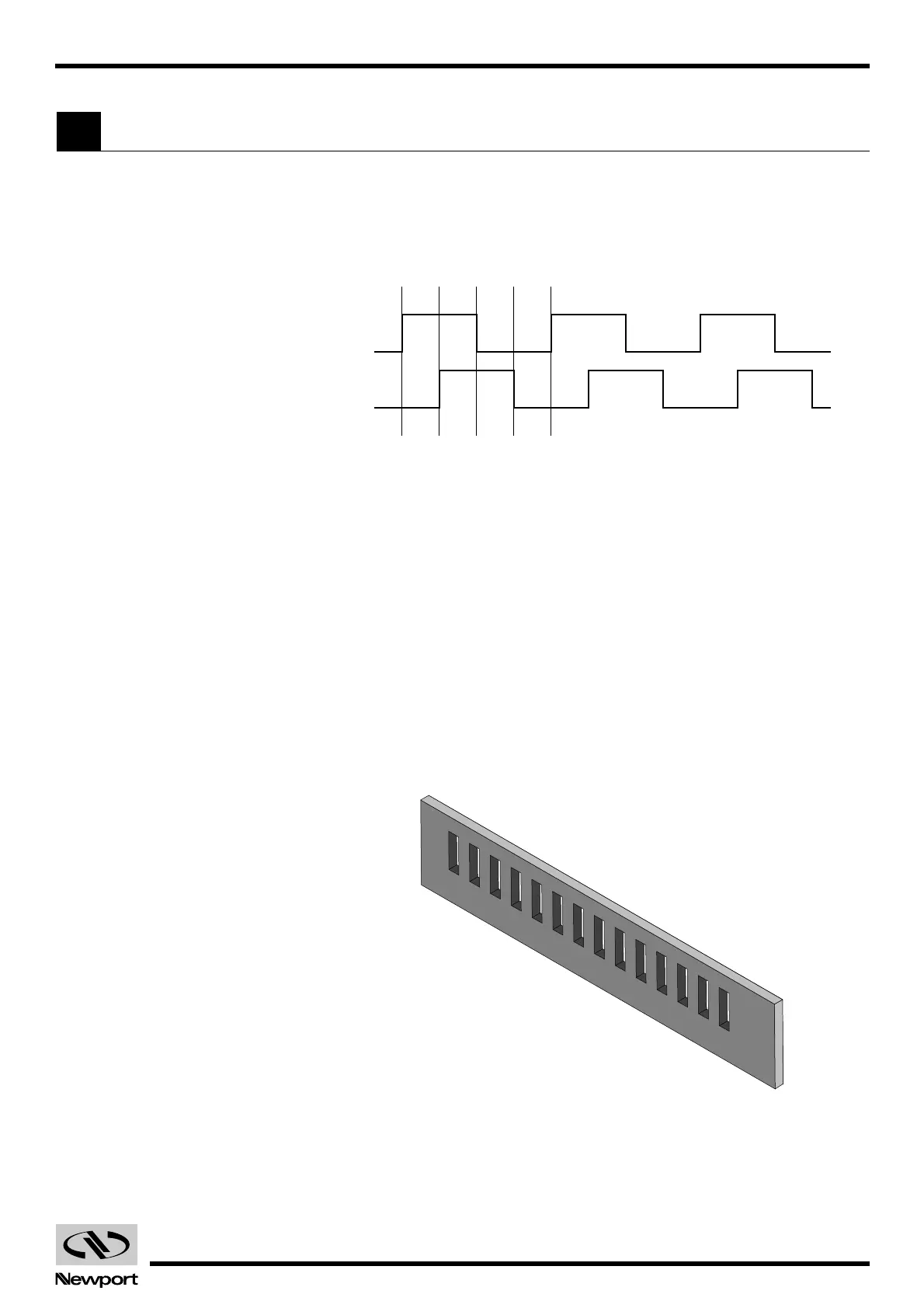
The main characteristic of an incremental encoder is that it has a 2-bit gray
code output, more commonly known as quadrature output (Fig. 4.26).
Fig. 4.26 — Encoder Quadrature Output.
The output has two signals, commonly known as channel A and channel B.
Some encoders have analog outputs (sine - cosine signals) but the digital
type are more widely used. Both channels have a 50% duty cycle and are
out of phase by 90°. Using both phases and an appropriate decoder, a
motion controller can identify four different areas within one encoder
cycle. This type of decoding is called X4 (or quadrature decoding), mean-
ing that the encoder resolution is multiplied by 4. For example, an encoder
with 10 µm phase period can offer a 2.5 µm resolution when used with a X4
type decoder.
Physically, an encoder has two parts: a scale and an read head. The scale is
an array of precision placed marks that are read by the head. The most
commonly used encoders, optical encoders, have a scale made out of a
series of transparent and opaque lines placed on a glass substrate or
etched in a thin metal sheet (Fig. 4.27).
Fig. 4.27 — Optical Encoder Scale.
The encoder read head has three major components: a light source, a mask
and a detector (Fig. 4.28). The mask is a small scale-like piece, having iden-
tically spaced transparent and opaque lines.
Artisan Technology Group - Quality Instrumentation ... Guaranteed | (888) 88-SOURCE | www.artisantg.com
 Loading...


