EDH0162En1040 – 06/99 8.18
MM4005 Appendix C — Connector Pinouts
C.10 Pass-Through Board Connector (25-Pin D-Sub)
WARNING
This pass-through board connector takes the place of the motor interface
connector only if this axis is connected to an external motor driver.
Pin # Designation
1 —
Ground
2 — N.C.
3 —
Mechanical Zero
4 — – End-of-Travel
5 — + End-of-Travel
6 — Driver Fault Signal
7 — Encoder Channel A
8 — Encoder Channel B
9 — Index Pulse I
10 — Pulse Command
(1)
11 — DirectionCommand
(1)
12 — ±10 V Analog Input
(2)
13 — N.C.
14 —
0 V Encoder Supply
15 — Driver Inhibition Command
16 — N.C.
17 — N.C.
18 — N.C.
19 —
Encoder Channel /A
20 — Encoder Channel /B
21 — Index Pulse /I
22 — 0 V logic
23 — 0 V logic
24 — N.C.
25 —
Reference for ±10 V Analog Input
1)
Stepper Motor Driver.
2)
DC Motor Driver.
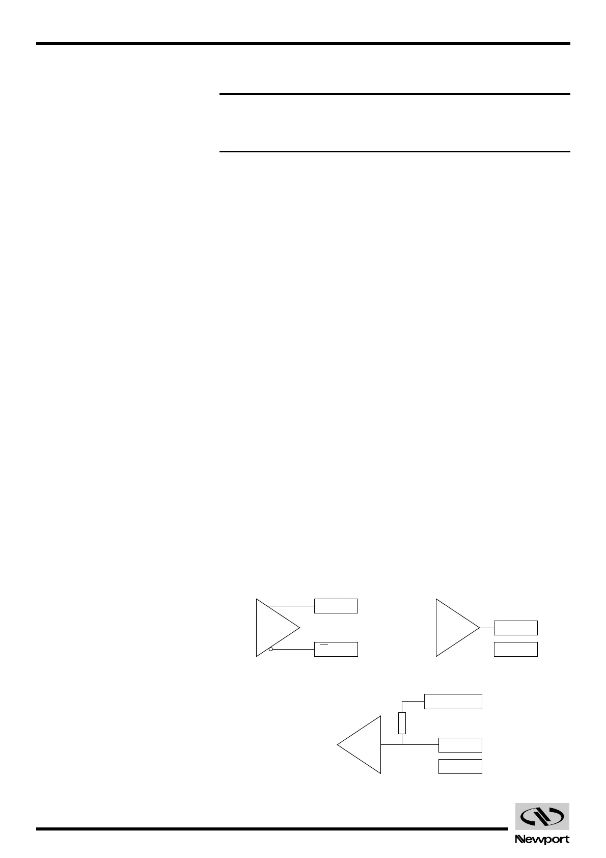
Fig. C.9 — DiFF. Output Type. Fig. C.10 — Open Collector Output Type.
Fig. C.11 — TTL Input Type.
Artisan Technology Group - Quality Instrumentation ... Guaranteed | (888) 88-SOURCE | www.artisantg.com
 Loading...


