1.15 EDH0162En1040 – 06/99
MM4005 Introduction
1.3.5 Front Panel Description
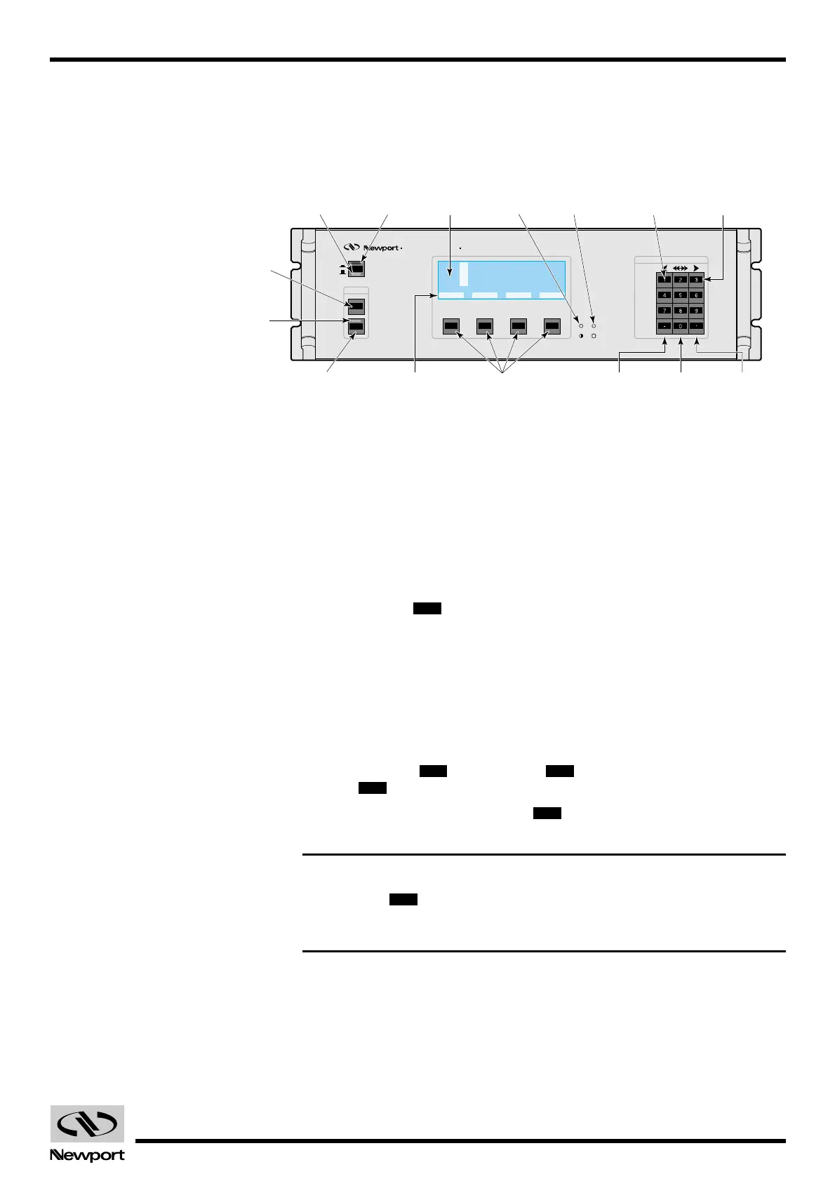
A general view of the front panel is shown in Fig. 1.7. There are three dis-
tinct areas, from left to right: power controls, a display and function keys,
and a keypad.
Fig. 1.7 — MM4005 front panel.
1.3.5.1 Power Stand-by
Use this button for your everyday controller power ON/OFF switching.
Power is switched through a relay, not directly as it is through the main
power switch on the rear panel. For this reason, a low power, low voltage
(12V) auxiliary power supply is always on when the main power switch in
the back is ON.
To differentiate from the rear main power switch, this button is called
“Power Stand-by ”.
The power stand-by switch has two LED indicators. A red LED on top, indi-
cates that the controller is powered OFF but the rear power switch is ON.
This is the “Stand-by” mode. A green LED below, indicates the controller
power ON condition.
1.3.5.2 Motor On/Off
For convenience and safety reasons, the power to the motors can be con-
trolled separately. This is done from the front panel through two buttons
labeled MOTOR and MOTOR . For easier identification, the
MOTOR button has a red bezel.
A green LED on top of the MOTOR provides a quick visual indication
of the motor Power ON condition.
NOTE
The MOTOR button is a normally closed switch wired in series with
the two Motor Interlock switch connections on the rear panel. For the
motors to turn on, the entire circuit must be closed.
OFF
ON
OFF
ONOFF
I/O
Artisan Technology Group - Quality Instrumentation ... Guaranteed | (888) 88-SOURCE | www.artisantg.com
 Loading...


