8.15 EDH0162En1040 – 06/99
MM4005 Appendix C — Connector Pinouts
C.7 RS-232C Interface Cable
The reason some pins are jumpered in the controller as described in Fig. C.3
is to override the hardware handshake when an of-the-shelf cable is used for
the RS-232C interface. This guaranties proper communication even when
the handshake cannot be controlled from the communication software.
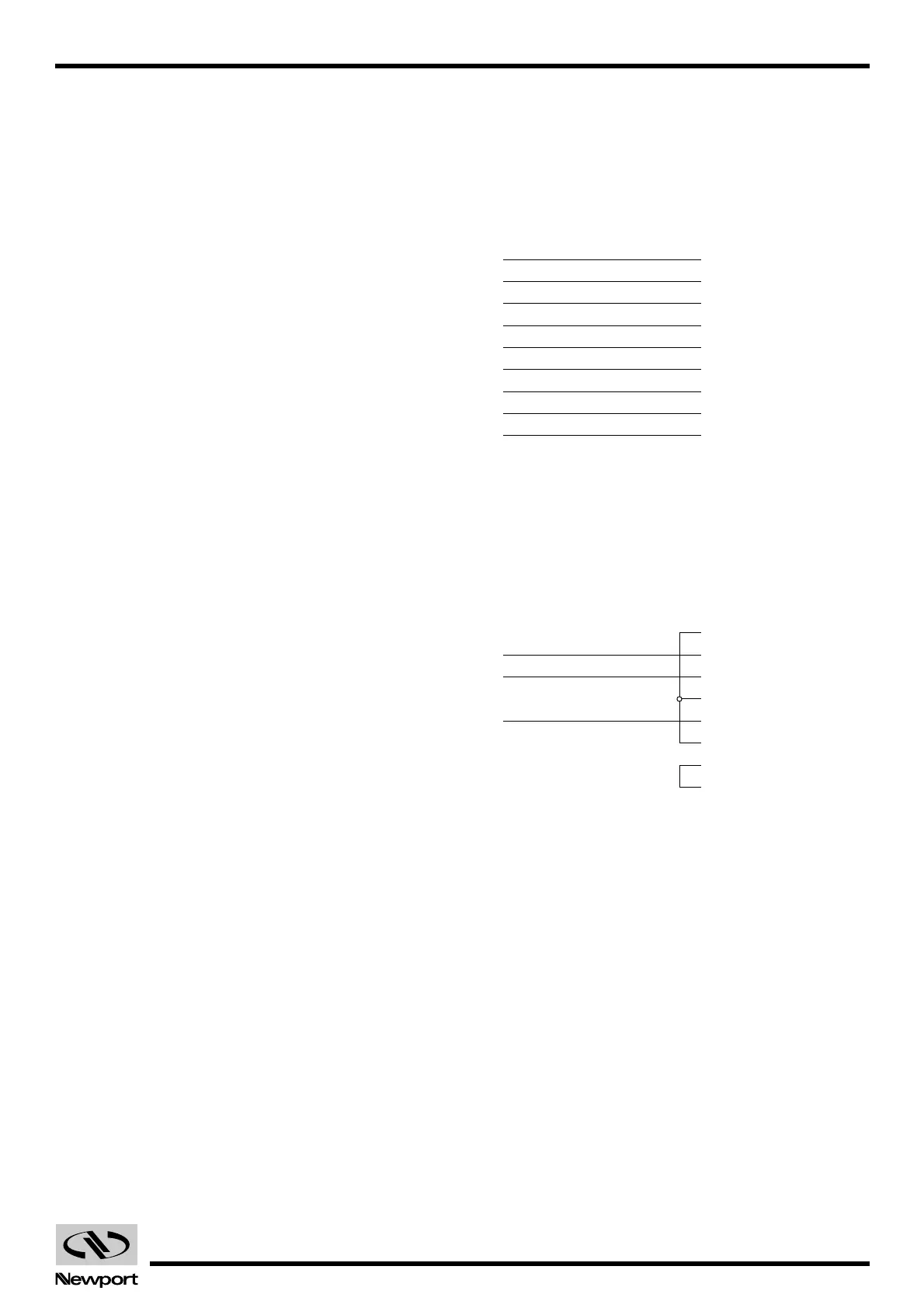
Fig. C.4 shows a simple pin-to-pin cable with 9 conductors.
Fig. C.4 — Conductor, pin-to-pin RS-232C interface cable.
If you want to use a three conductor cable, you must use a cable config-
ured as in Fig. C.5 to get the same hardware handshake override.
Fig. C.5 — Conductor RS-232C interface cable.
If your computer or terminal uses a 25-pin connector for the RS 232C inter-
face, you can use an off-the-shelf 25 to 9-pin adapter and one of the two
cables described above.
If you do not wish to add an adapter, you can use an off-the-shelf 9 to 25-pin
RS-232C cable or build one like in Fig. C.6.
Artisan Technology Group - Quality Instrumentation ... Guaranteed | (888) 88-SOURCE | www.artisantg.com
 Loading...


