8.11 EDH0162En1040 – 06/99
MM4005 Appendix C — Connector Pinouts
C.4 Auxiliary Connector (25-Pin D-Sub)
This connector is used for the MOTOR indicator, the frequency gener-
ator output, the analog inputs and outputs and the synchronisation pulses.
The analog outputs are only available in option.
The logic outputs are open-collector type and are rated for maximum 30 V
and 40 mA (Fig. C.2). To drive logic input, they require a pull-up resistor.
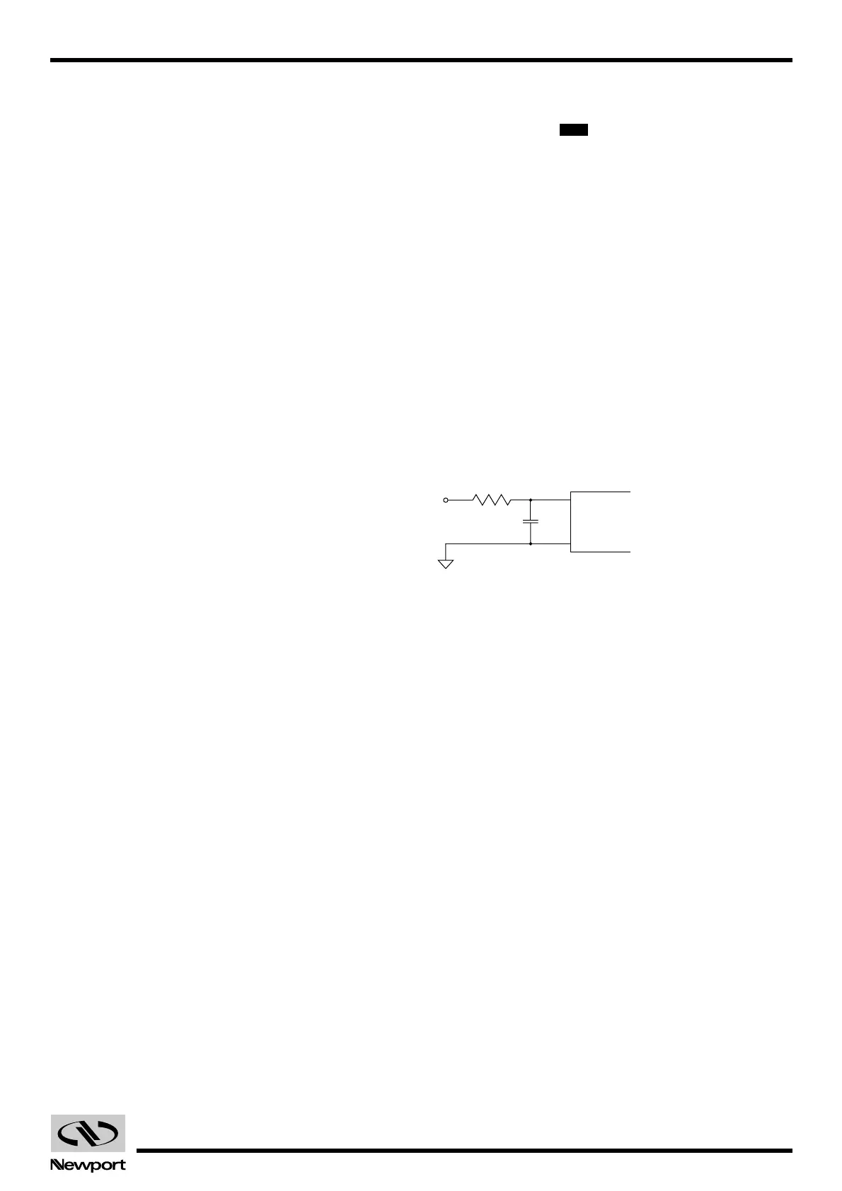
The analog inputs and outputs have 12 bits resolution.
The analog inputs are multi-range, software programmable. The available
ranges are ±10V, ±5V, 0-10V, 0-5V. See the RA and AM commands for more
programmation details. In all cases, analog inputs must be below ±10 V.
The impedance of the converter inputs is typically 10kOhms. The maxi-
mum input current is ±300µA. The maximum offset error is ±10 LSB, and the
maximum gain error is ±10 LSB. The input characteristics of the analog
inputs are in Fig. C.1.
The value of 1 LSB depends of the used range:
• 1 LSB is: 20 V / 4096 ≈ 5 mV for the ±10 V range.
• 1 LSB is: 10 V / 4096 ≈ 2.5 mV for the ±5 V range and 0-10 V range.
• 1 LSB is: 5 V / 4096 ≈ 1.25 mV for the 0-5 V range.
Fig. C.1 — Equivalent circuit of an analog input.
The analog outputs range is ±10 V. The maximum offset error is ±200 mV,
and the maximum gain error is ±10 LSB. The output setting time is typically
6 µsec. These outputs are voltage outputs (output current less than 1 mA),
so to use them properly, they must be connected to an impedance higher
than 10 kW. 1 LSB is: 20 V / 4096 ≈ 5 mV.
Pin # Description
1 — DGND
2 — N.C.
3 — UTIL
4 — UTIL
5 — UTIL
6 — UTIL
7 — UTIL
8 — N.C.
9 — N.C.
10 — O
A LOW signal indicates that Motor Power is ON.
11 — O Pulse synchronized to one AXIS, see PB, PE, PI and PS com-
mands.
12 — O Pulse synchronized to a trajectory, see NB, NE, NI, NN and
NS commands.
13 — DGND
14 — I
Analog Input 1.
15 — I Analog Input 2.
16 — I Analog Input 3.
Artisan Technology Group - Quality Instrumentation ... Guaranteed | (888) 88-SOURCE | www.artisantg.com
 Loading...


