NewSonic SonoDur2 Issue 04 09/2016 Page 32
The force should be exclusively applied starting from the probe closure head via the palm of the hand
or the thumb. Other fingers are solely there for the probe guidance free of side-forces. A second
hand can serve for this purpose as well. In any case the force vector must point into the direction of
the oscillation rod axes in order to avoid disturbances by lateral forces. When the probe attachment
sleeve is unscrewed, small and narrow test positions can be also securely measured (see Figure 7.27,
SONO-100H, HV10 to test cutting edges on construction steel according to EN ISO 1090).
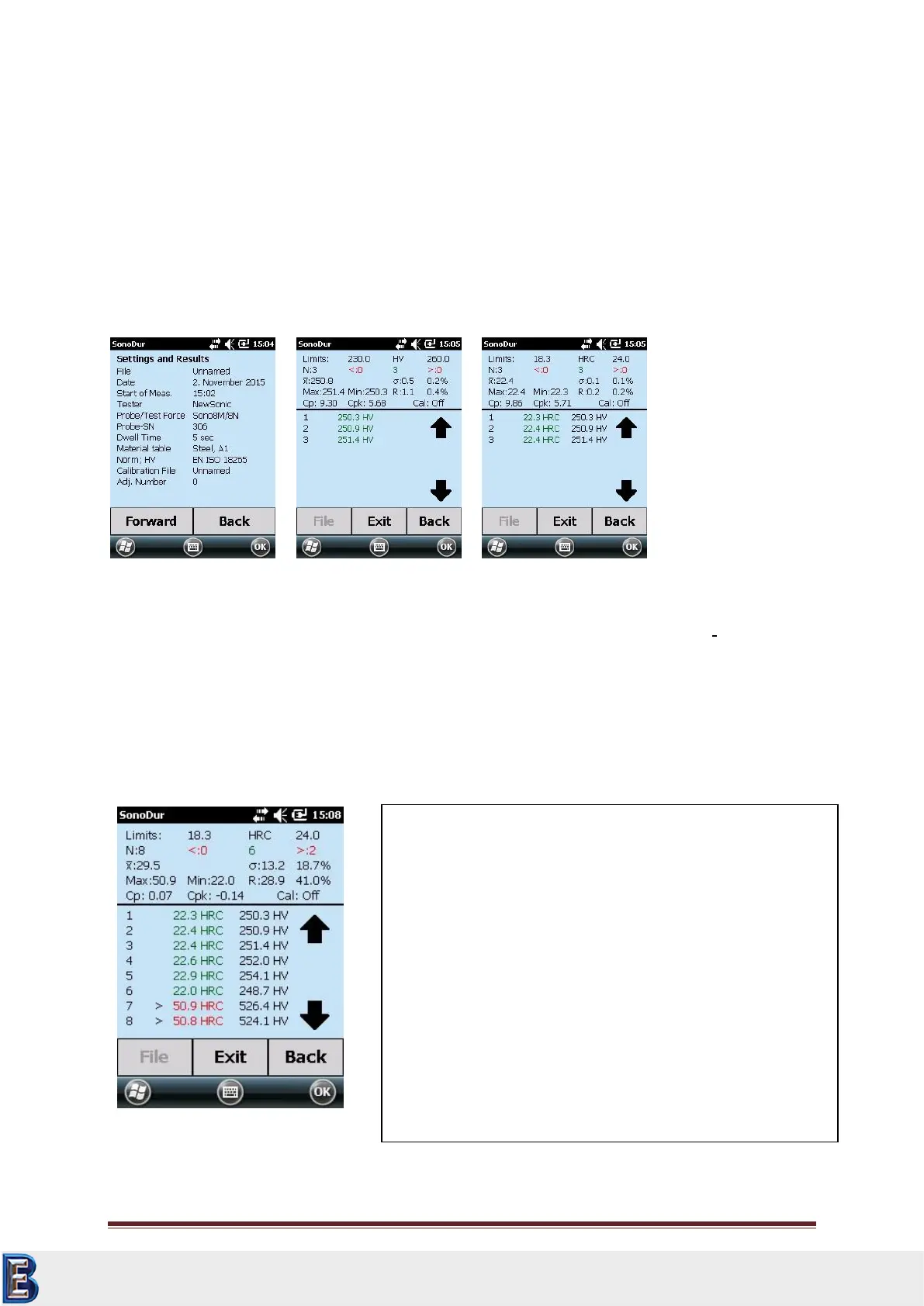
7.5 Information Menu
Display of current device settings, statistic and processing of measurement data.
All relevant information is displayed at a glance (Figure 7.28) and via "Forward" button, one receives
information on the measurement results (Figure 7.29 and Figure 7.30). Figure 7.30 shows the same
result as Figure 7.29 with the only difference, that the original measurement values (HV) have been
converted to HRC, whereas the results of the original scale are always carried along for information
purpose. The relevant tolerance thresholds will be automatically converted from the original scale to
the re-evaluated hardness scale along with the summarized results for the average value, overline X,
mean error of individual measurement σ, range R, minimum and maximum.
Please see Appendix for further explanations on terms and formulas (Formulas and Terms, page 68).
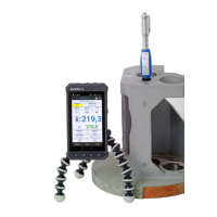
Interpretation of results (in this case, in HRC):
Thresholds: Minimum, maximum, hardness unit HRC
Measurement quantity N = "8", thereof "6" measurements
within the tolerance range, "2" above, "0" below.
Average value, overline X =29.5 HRC, σ = 13.2 HV or 18.7 % of
overline X
Extreme values: Max = 50.9 HRC, Min = 22.0 HRC, R = 28.9
HRC or 41.0 % of overline X
Process parameters: Cp = 0.07 or Cpk = -0.14; Cal= off
(dimensionless, standard steel)
Individual results: Green = Ok, Red = beyond tolerance, > =
above and < = below, X = deleted, Black = Vickers values for
comparison.
Your Complete Source for
Testing Equipment. Since 1969!
www.BergEng.com
Berg Engineering & Sales Company, Inc.
Tel 847-577-3980
info@bergeng.com