SHAPING THE FUTURE OF SATELLITE COMMUNICATIONS
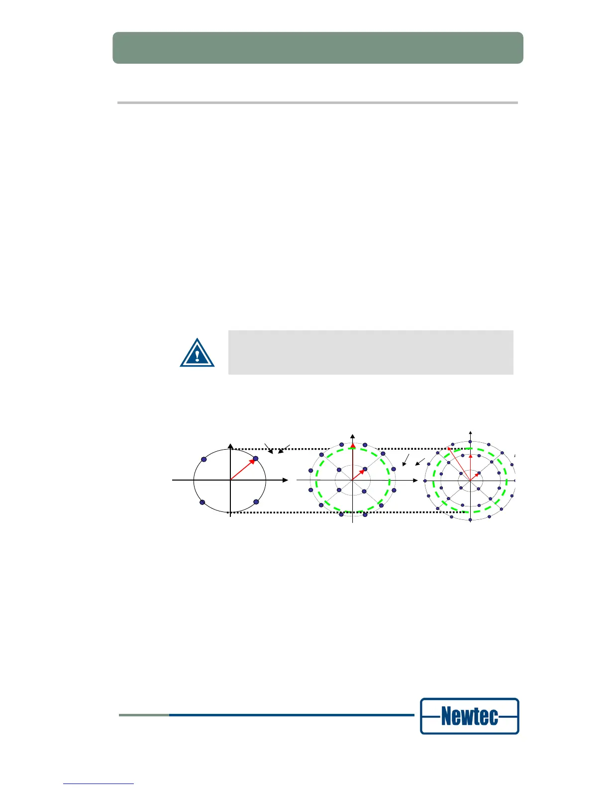
9.9 Modulator Constant Power / RIM
The Modem features two Output Level Plans:
• Constant Power: in this plan, output power is kept equal for the different
ModCods. This is the default mode of operation;
• Constant Rim: in this plan, the outer ring of the symbol constellation is kept
equal for the different ModCods. As a consequence, different ModCods are
transmitted with different output power. This mode is intended to operate with a
saturated transponder. It avoids excessive input back-off for QPSK, 8PSK
16APSK ModCods during VCM/ACM operation. The lower ModCods can
indeed be operated closer to saturation. Due to the dynamic level changes this
mode is only possible with "Manual Gain Control". As such, the ALC on the
transponder should be disabled. Since the highest outer ring level occurs for a
ModCod of 32APSK-3/4, this ModCod is used as the reference for the output
power level setting. The other ModCods are transmitted with higher power:
- 16APSK : +1 dB
- QPSK and 8PSK : +2 dB
When operating in constant RIM mode:
• Equalink should be disabled;
• Transponder ALC should be disabled.