SHAPING THE FUTURE OF SATELLITE COMMUNICATIONS
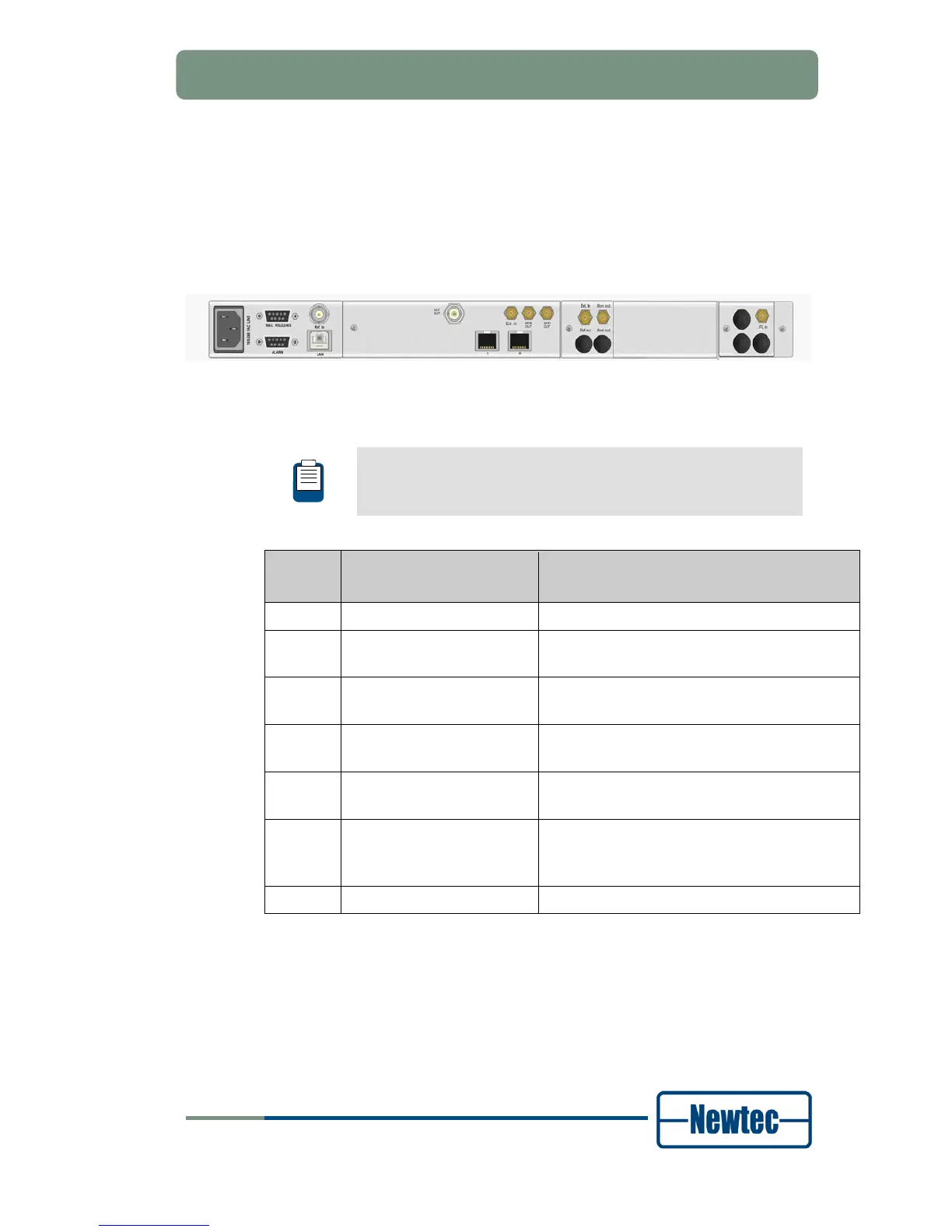
4.2.3 EL 170 IP Satellite Modulator Back Panel
The figure below shows the possible connections on the modulator. The back
panel connections available depend on the specific hardware configuration of your
device and will differ from the back panels in the figures below. Only a subset of
the shown connections will be available on your device.
Figure 22 - EL170 IP Satellite Modulator Back Panel
The sub back panels used per ordering option is listed in the following table.
We refer to section Options on page ‘xiii ‘for ordering information.
We refer to section 4.2.2 for the description of the different sub
back panels.
Option Back Panel Combination
Not Used Connectors
BP-<number>/<connector>,<connector>
Default BP 01 BP 01/2
AA-03 BP 01
BP 07
BP 01/2
BP-07/5
AA-02 BP 01
BP 02
BP 01/2,3,4
BP02/3,4
AA-12 BP 01
BP 06
BP 01/2
AA-13 BP 01
BP 06
BP 01/2
AA-06 BP 01
BP 02
BP 05
BP 01/2,3,4
BP 02/3, 4
BP 05/1,3,4
AA 18 BP 01 BP 01/2