SHAPING THE FUTURE OF SATELLITE COMMUNICATIONS
7.3 EL 970 Demodulator
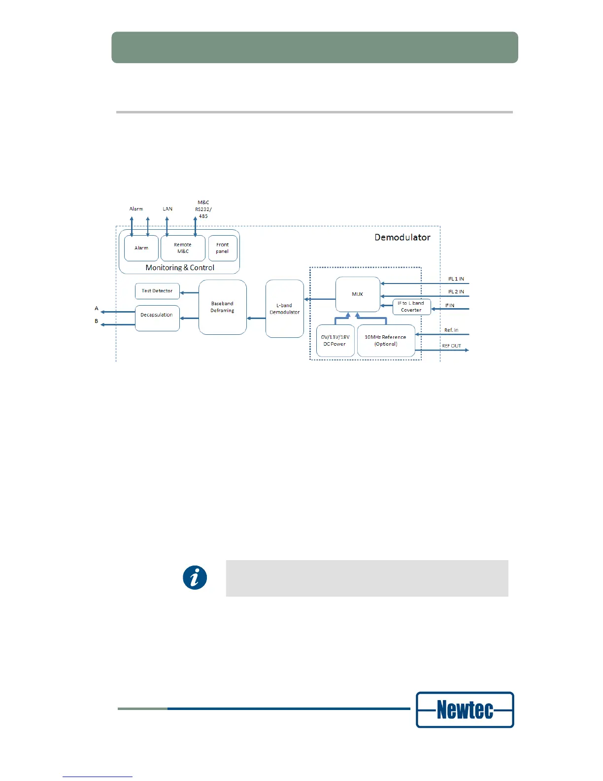
In this diagram the demodulator is split up into the following functionalities:
• Monitor and Control;
• Demodulator Functionality.
Figure 56 - Combined block diagram – L-band
The EL970 has a dual L-band input. The active input is selected by the user and
can provide DC power and frequency band selection signals compatible with most
professional and commercial LNBs.
The L-band signal is demodulated by the L-band Demodulator. This demodulated
signal is deframed and decapsulated. The data is available on the Ethernet
connector A or B depending which one is activated by the user.
Test Generator
The demodulator is equipped with a build in test generator. This generator can be
used to detect/monitor IP data.
Option IF OUT
Optionally, one L-band input can be replaced by an IF input.
This option is not shown in the block diagram.