User Manual for EL170/970/470 IP Satellite Modulator/
Demodulator/Modem
SHAPING THE FUTURE OF SATELLITE COMMUNICATIONS
4.2 Back Panel Description
The back panel consists of several modules depending on the hardware that is
installed.
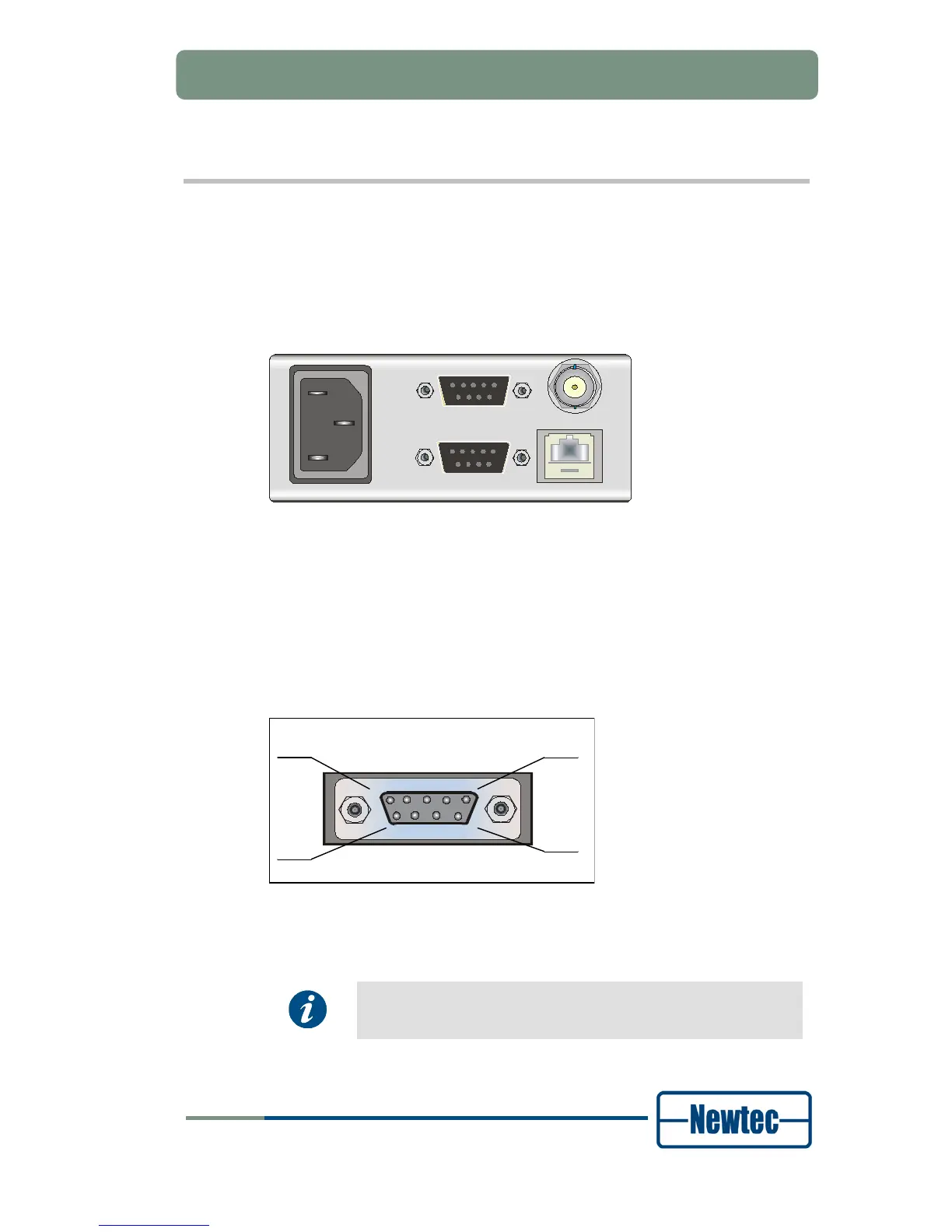
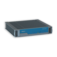
4.2.1 PSU, M&C Interface and External 10.0 MHz Reference Input
ALARM
10/100Base-T
Ref. In
M&C RS232/485
100-260 VAC LINE
Figure 17 - PSU, Monitor and Control and External 10 MHz Reference
Power socket
This equipment is provided with a protective earth ground incorporated in the
power cord. The mains plug shall only be inserted in a socket outlet provided with a
protective earth contact. Any interruption of the protective conductor, inside or
outside the instrument, is likely to make the instrument dangerous.
Serial Monitoring and Control via RS485/RS232
Figure 18 - Serial Monitoring and Control Connector
The device contains the hardware for the RS485 and RS232 interface.
Select the type of serial interface via the front panel or via the GUI
but not via the serial port itself.