Safety
information
Introduction
Product
Information
System
design
Mechanical
Installation
Electrical
Installation
Getting
started
Optimization Parameters
Technical
data
Component
sizing
Diagnostics
UL
Information
22 Unidrive M Regen Design Guide
Issue Number: 4
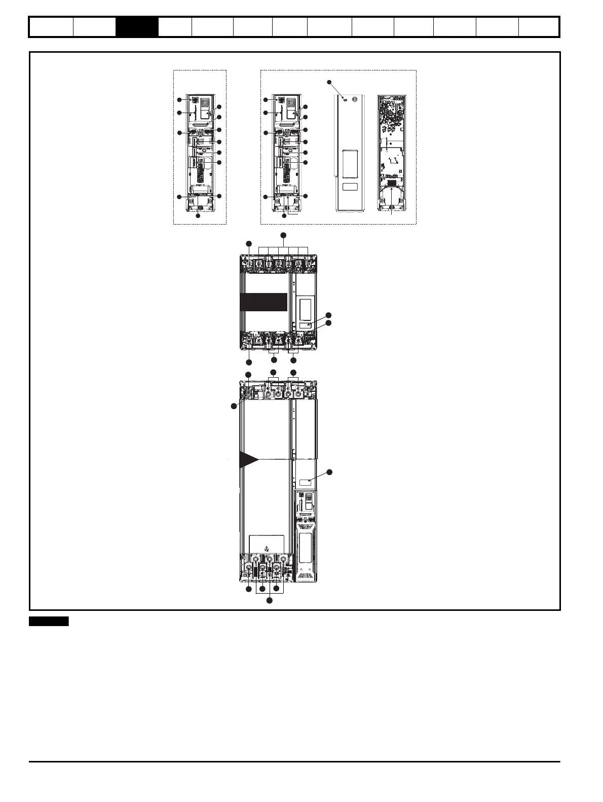
Figure 3-5 Features of the Unidrive M size 11
The rectifier and Unidrive 11D are fitted with dual input power terminals (2 x L1, L2, L3 on the rectifier and 2 x +DC, -DC on the inverter). Ensure that
cables to both of the terminals are installed.
14
15
16
15
18
14
11D
2
Master Pod
Output to follower
1
2
3
4
5
6
7
8
9
10
11
12
Follower Pod
Input from Master /
Output to follower
Cover
Base
1
4
3
Standard Pod
1
2
3
4
5
6
7
8
9
10
11
12
Single drive systems Parallel systems
15
16
14
Size 1
1
Rectifier
15
16
14
15
16
14
3
2
14
13
17
1419
Key
1. Rating label 6. Option module slot 3 11. NV media card slot 16. DC bus output -
2. Identification label 7. Relay connections 12. Keypad connection 17. AC supply connections (U, V, W)
3. Status LED 8. Position feedback connections 13. Charging input (L1, L2, L3) 18. Braking terminal
4. Option module slot 1 9. Control connections 14. Ground connections 19. Internal EMC filter (must be removed)
5. Option module slot 2 10. Communications port 15. DC bus output +

 Loading...


