Do you have a question about the Nilfisk-Advance Advenger 3400ST and is the answer not in the manual?
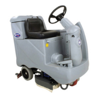
| Model | Advenger 3400ST |
|---|---|
| Category | Floor Machine |
| Type | Rider Scrubber |
| Cleaning path | 34 inches |
| Power source | Battery |
| Battery Voltage | 36V |
| Brush Width | 34 inches |
| Working Width | 34 inches |
| Recovery tank capacity | 30 gallons |
Manual's purpose is basic troubleshooting, maintenance, and repairs within 2-3 hours.
Overview of Advenger/BR 755, 855, ST floor scrubbers, deck sizes, pressure, flow rates.
Repairs should be performed by authorized service centers with factory-trained personnel.
Location of Model and Serial Number for ordering parts and support.
Explains DANGER, WARNING, and CAUTION symbols used to signal hazardous conditions.
Specific safety guidelines for operation, maintenance, and handling the machine.
Lists other manuals and resources available on the Nilfisk-Advance website.
Lists essential tools and software required for troubleshooting and repair.
Instructions and cautions for safely transporting the machine on a truck or trailer.
Illustrates safe locations for lifting the machine with a jack.
Explains the function of the emergency stop button and its limitations.
Machine specifications including voltage, dimensions, weight, sound, and vibrations.
Details on batteries, onboard charger, and drive system specifications.
Information on solution flow rates for different scrub modes and detergent ratios.
Specifications for vacuum motors and water lift capabilities.
Technical details on scrub deck types, brush/pad sizes, motor specs, and scrub force.
Procedure and caution for manually overriding the drive wheel brake for towing.
Labeled diagram of the machine's front right-hand side components.
Labeled diagram of the machine's rear left-hand side components.
Detailed explanation of the control panel buttons and display indicators.
Detailed explanation of the control panel buttons and display indicators for REV models.
Detailed explanation of the control panel buttons and display indicators for ST models.
Step-by-step guide on how to operate the machine, including scrub and vac functions.
Table listing error codes, fault descriptions, affected systems, and page references.
Table detailing LED codes, explanations, and possible causes for speed control faults.
Table showing systems disabled for each error code to aid diagnostics.
Explains how scrub, vacuum, and recovery systems are controlled via different modes.
Explains system control modes for ST models.
Refers to system control modes for functionality explanation.
Lists error codes, measurements, and troubleshooting steps for squeegee lift actuator issues.
Common squeegee problems and their possible causes for Advenger/BR 755, 855 and ST.
Instructions for adjusting squeegee tilt and wheel height for optimal performance.
Step-by-step procedure for replacing the squeegee lift actuator.
Procedure for adjusting the squeegee lift actuator drive nut settings.
Procedure for replacing the squeegee lift cable on Advenger/BR 755, 855 models.
Procedure for replacing the squeegee lift cable on ST models.
Instructions for adjusting the squeegee lift cable tension on ST models.
Steps for removing the steering column shroud for access.
Explains how pressing the Scrub On button activates scrub deck, brushes, vacuum, and solution.
Describes scrub mode and floor finish removal mode for REV models.
Explains scrub system operation for ST models.
Lists error codes, fault descriptions, and troubleshooting for brush motor control.
Lists error codes and troubleshooting for scrub deck lift actuator.
Addresses specific scrub system malfunctions not covered by error codes.
Step-by-step procedure for replacing the scrub deck lift actuator.
Procedure for adjusting the scrub deck lift actuator drive nut.
Procedure for timing the spring housing for the REV model actuator.
Instructions for removing the scrub deck for Disc and REV models.
Procedure for removing the brush motor for Disc models.
Procedure for removing the brush deck motor for REV models.
Instructions for removing and installing the drive motor, bearing, and eccentric.
Procedure for removing the motor plate and isolators for REV models.
Procedure for removing the brush head and motor end plates.
Instructions for removing the scrub deck for Cylindrical models.
Procedure for removing the brush motor for Cylindrical models.
Explains how the recovery system is controlled via the control board and vac motors.
Explains recovery system control for ST models.
Lists error codes, fault descriptions, and troubleshooting for vacuum motors and contactors.
Addresses common recovery system problems like poor water pickup and vacuum motor issues.
Procedure for removing the recovery tank and vacuum motor.
Explains how the solution system is controlled by the control board and solenoid valve.
Lists error codes, measurements, and troubleshooting for solution and AXP/EDS systems.
Addresses problems like inadequate solution flow and incorrect flow rates.
Illustrates the components and flow of the solution system.
Explains how deck size, flow rate, and liquid level sensor control the solution system.
Procedure for replacing the solution solenoid valve.
Describes the Curtis 1228 speed control and its role in drive wheel operation.
Lists error codes and troubleshooting steps for wheel drive system issues.
Procedure for replacing the drive wheel assembly.
Procedure for replacing the drive tire using a tire pulling kit.
Notes and steps for installing the drive hub and wheel/tire assembly.
Procedure for inspecting and replacing carbon brushes in the drive wheel motor.
Procedure for replacing the rear wheels, including bearing maintenance.
Instructions for accessing the electrical panel and its components.
Procedure for measuring throttle potentiometer voltage in neutral position.
Details pinouts and test points for control board connectors J1, J2, and J3.
Provides measurement values for REV deck connector J1.
Provides measurement values for connector J2.
Provides measurement values for connector J3.
Procedure for checking the Curtis speed control installation.
Procedure for removing and replacing the operator control panel assembly.
Explains how to enter and use Service Test Mode for troubleshooting.
Information on programmable settings for control boards.
Table detailing programmable settings and options for Advenger/BR 755, 855.
Table detailing programmable settings and options for ST models.
Explains how to enter and use Service Test Mode for ST models.
Instructions for entering and navigating hidden menus for REV models.
Details the various program options available for REV models.
Explains how to use Service Test Mode for diagnostic tests on REV models.
Describes how to interpret LCD feedback during service test mode for input tests.
Daily, weekly, and monthly maintenance tasks for operator use.
Maintenance tasks for machines stored for extended periods.
Maintenance tasks recommended for service technicians, including intervals.
A checklist for operational inspections and defect identification.
Labeled diagram showing the location of electrical components.
Schematic diagram of the electrical system for Disc and Cylindrical decks.
First sheet of the wiring diagram for REV decks.
Second sheet of the wiring diagram for REV decks.
Diagram illustrating the wiring harness for REV decks.
Labeled diagram showing the location of electrical components for 2800ST/3400ST models.
Schematic diagram of the electrical system for 2800ST/3400ST models.