Installation
1040-0011 Revision 26
Connector J10 (RS-232) Signal Descriptions
Odd-numbered Pins (1 – 9)
Even-numbered Pins (2 – 10)
RS232_RX0
Data input from connected device
RS232_RTS0
Request to send to connected
device
RS232_TX0
Data output to connected device
RS232_CTS0
Clear to send from connected
device
N/C
Reserved for future use
GND
Digital ground reference
CHASSIS
Expected to be tied to earth
ground
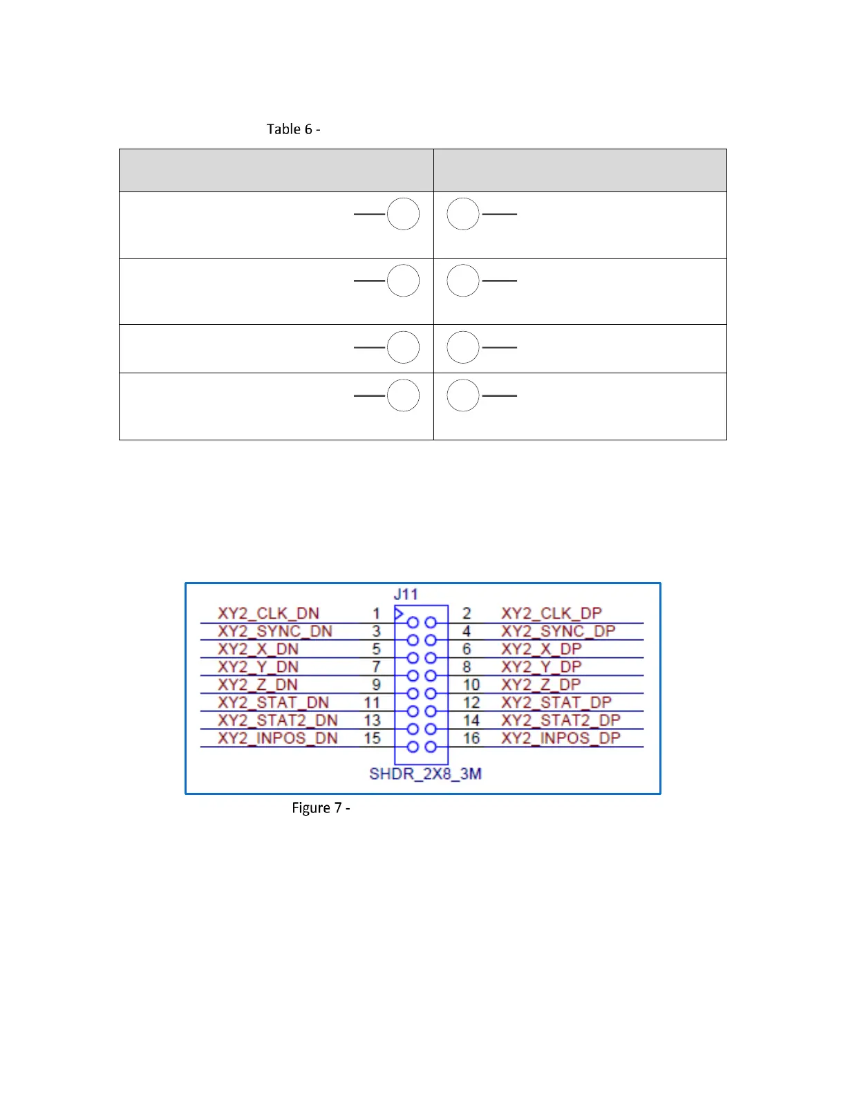
4.5.3 XY2-100 Signal Pinouts (Connector J11)
The following figure contains the pinout drawing for Connector J11 (XY2-100).
Connector J11 (XY2-100) Pinouts
The following table contains a full description of the signal for each pin in the J11 Connector.