Appendix D - SMC-LRS-04 High-power Laser Adapter
1040-0011 Revision 79
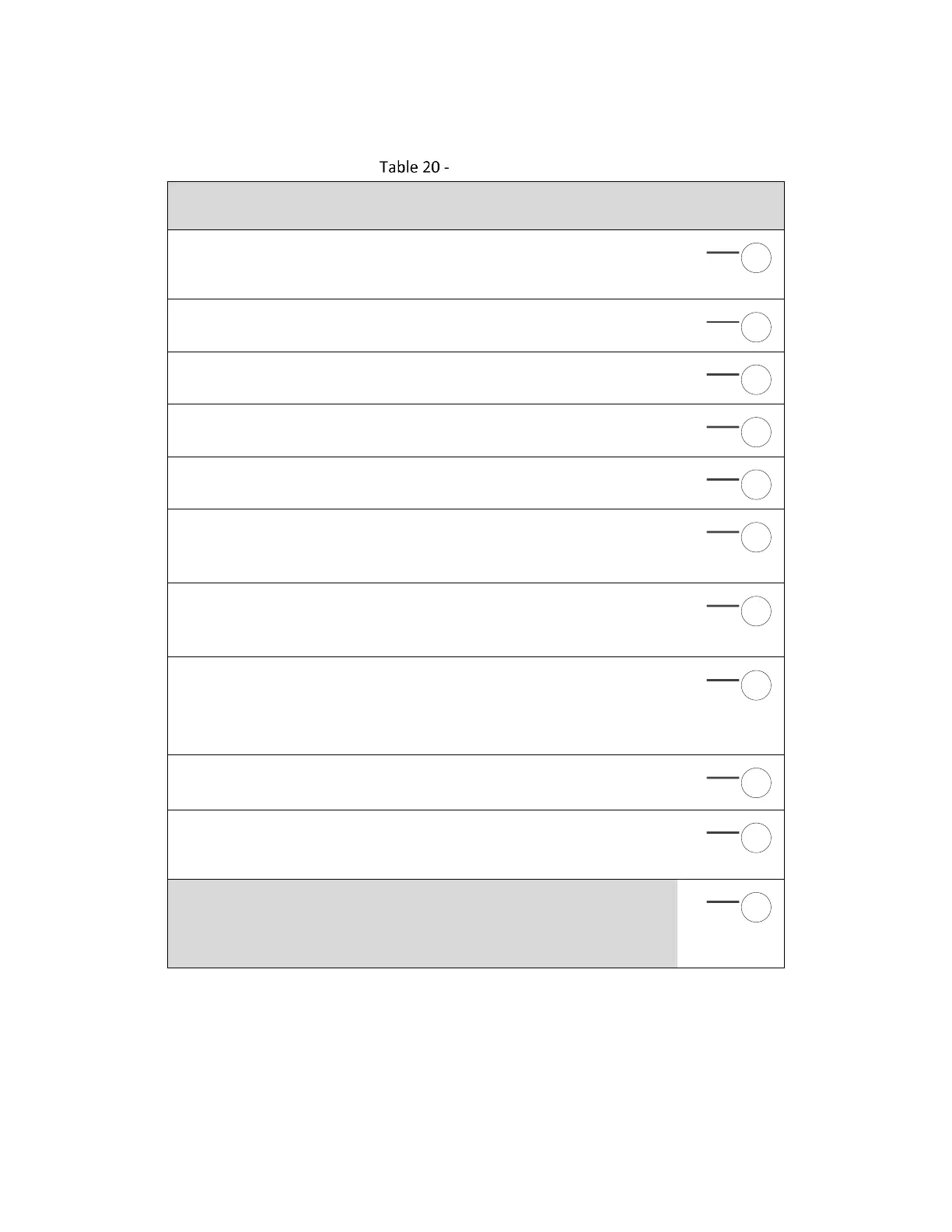
8.3.1 J2 - Laser Signal Set 1
Laser Signal Set 1
+24V
This pin provides external voltage to the high-voltage digital signal drivers. It
is also connected to the SMC 24V connector J3.
LASER_ENABLE_BUF
High-voltage buffered version of the SMC LASER_ENABLE signal
LASER_GATE_BUF
High-voltage buffered version of the SMC LASER_GATE signal
LASER_MOD1_BUF
High-voltage buffered version of the SMC LASER_MOD1 signal
LASER_POINTER_BUF
High-voltage buffered version of the SMC LASER_POINTER signal
GND
Digital and analog ground reference
NOTE: Incorrectly labeled as “ANA” on Rev C silkscreen
LASER_ANALOG1
0 to 10V analog laser power control
NOTE: Incorrectly labeled as “ANA_GT” on Rev V C silkscreen
LASER_ANALOG1_GATED
0 to 10V analog laser power control switching between 0V and the set voltage
synchronous with the LASER_GATE signal
NOTE: Incorrectly labeled as “GND” on Rev C silkscreen
LASER_LOCAL_MOD_SUPPLY
Voltage source for external circuitry that control local modulation behavior
LASER_LOCAL_MOD_CONTROL
Analog input control signal for regulating the duty-cycle of a local 10KHz
modulation source
LASER_LOCAL_ENABLE_N
If switched to GND, the local laser modulation source will be applied to the
differential LASER_MOD outputs on J3 and to the BNC connector. If not
connected, the SMC LASER_MOD1 modulation will be selected.