Installation
1040-0011 Revision 35
Connector J14 (MOTF-1) Signal Descriptions
Even-numbered Pins (2 – 10)
EXT_VCC5V0
5 Volts available for encoder
power
GND
Digital ground reference
AUX_GPO2
A marking job may contain an
instruction that causes a pause in
execution until this signal is
asserted by external equipment.
CHASSIS
Expected to be tied to earth ground
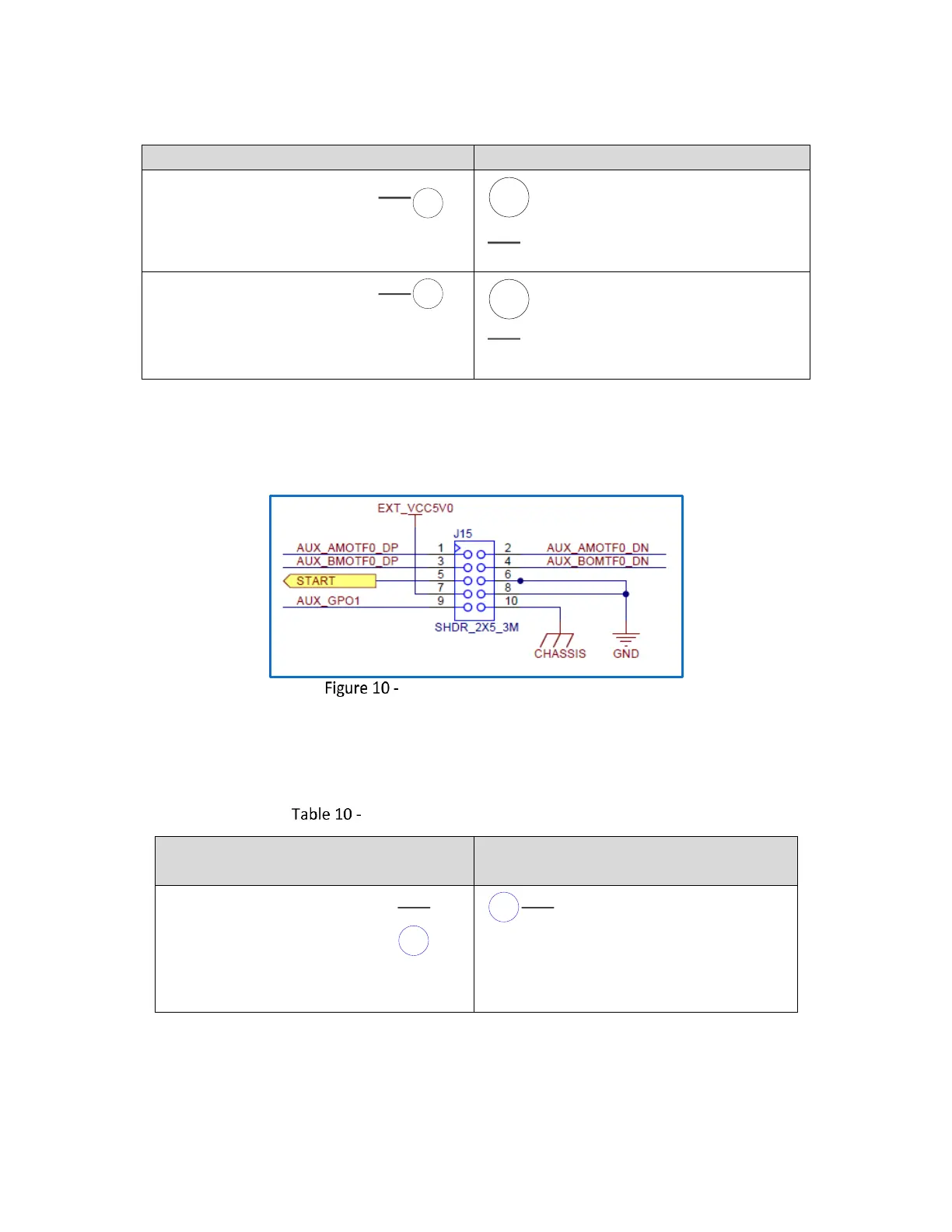
4.5.6 MOTF-0 Signal Pinouts (Connector J15)
The following figure contains the pinout drawing for Connector J15 (MOTF-0)
Connector J15 (MOTF-0) Pinouts
The following table contains a full description of the signal for each pin in the J15 Connector. These
signals are replicated from the Auxiliary I/O connector J13.
Connector J15 (MOTF-0) Signal Descriptions
Even-numbered Pins (2 – 10)
AUX_AMOTF0_DP
Primary mark-on-the-fly encoder
input. Expected to be connected
to an RS-485 positive “A” phase
differential signal or a 5V TTL
signal.
AUX_AMOTF0_DN
Primary mark-on-the-fly encoder
input. Expected to be connected
to an RS-485 negative “A” phase
differential signal.