EasyManuals Logo

Novanta ScanMaster User Manual

Novanta ScanMaster
103 pages
To Next Page IconTo Next Page
To Previous Page IconTo Previous Page
Page #91 background imageLoading...
Page #91 background image
Appendix D - SMC-LRS-04 High-power Laser Adapter
1040-0011 Revision 82
LASER_ANALOG1_GATED
1
2
3
4
5
6
7
8
9
10
11
12
J2
LASER_LOCAL_MOD_SUPPLY
GND
+24V
LASER_ENABLE_BUF
LASER_GATE_BUF
LASER_MOD1_BUF
LASER_POINTER_BUF
LASER_ANALOG1
LASER_LOCAL_MOD_CONTROL
LASER_LOCAL_ENB_N
10K
Circuitry supplied
by the user
GND
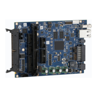
Remote Modulation Control Configuration
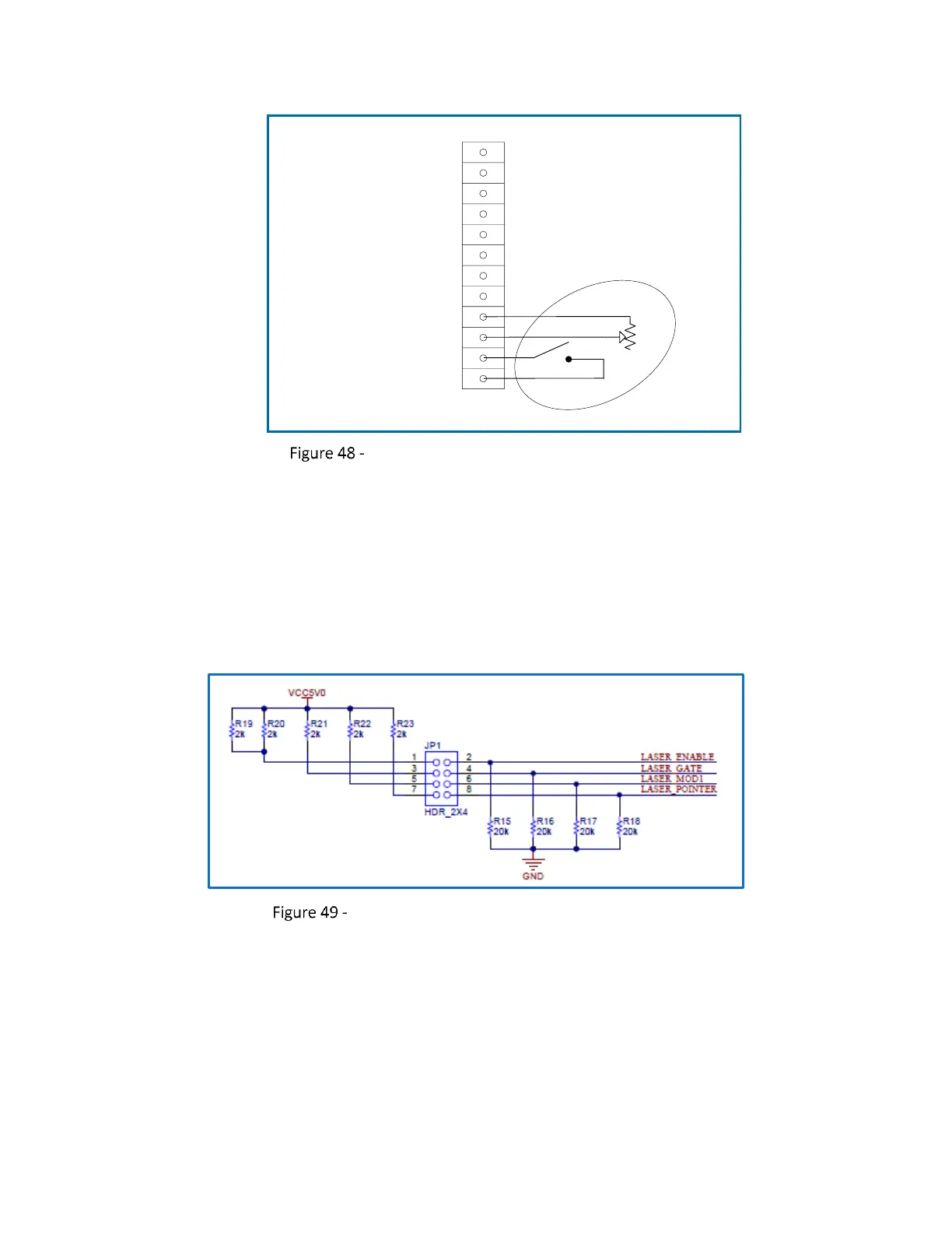
8.5 SELECTIVE PULL-UP/PULL-DOWN OF CONTROL SIGNALS
By default, the main laser control signals are actively pulled down to ground through 20K resistors as
shown in the following figure. If necessary, jumper selectable pull-up resistors may be applied to
permit setting these signals to a high state during power-up cycles. The use of these jumpers is laser
specific. Please consult your laser manual for best practices in this regard.
Control Signal Pull-up/Pull-down Configuration

Table of Contents

Questions and Answers:

Question and Answer IconNeed help?

Do you have a question about the Novanta ScanMaster and is the answer not in the manual?

Novanta ScanMaster Specifications

General IconGeneral
BrandNovanta
ModelScanMaster
CategoryController
LanguageEnglish