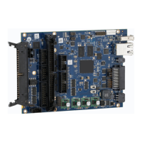
Extended Inputs Signal Conditioning
5.3.6 J7 and J9 – Extended Digital Outputs
These outputs are 5- to 24V-compatible open-collector drivers. The signal conditioning is shown
below in Figure 37 - Extended Outputs Signal Conditioning. These outputs are pulled up to +5V
through a diode for convenience of driving lightly loaded TTL devices, but are intended to be used as
sinking drivers where the load to be driven has one end attached to 24V. The drivers will then switch
the connected end of the load to ground.
Note: EXT_VCC5V0 is an internally supplied voltage. +24V is expected to be externally supplied. This
signal is also connected to the SMC main module +24V input in Section 4.5.1 ("Power Signal Pinouts
(Connectors J1 and J3)") on page 17.
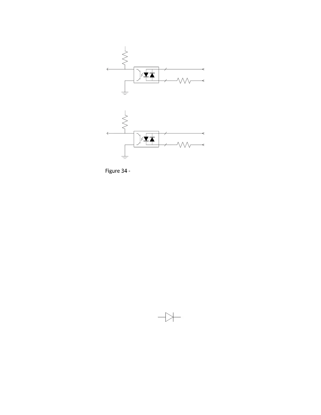
Note: +24V should not be left floating. If a 24V supply is not available, then connect EXT_VCC5V0 to
+24V through a diode: