Installation
1040-0011 Revision 39
Connector J16 (Control) Signal Descriptions
Odd-numbered Pins (1 – 19)
Even-numbered Pins (2 – 20)
AUX_BUSY
Asserted when a BeginJob
instruction is executed; de-
asserted when an EndJob
instruction is executed.
AUX_LASING
Asserted when marking is in
progress.
AUX_GPO1
A marking job instruction may
specify the state of this signal.
AUX_GPO2
A marking job instruction may
specify the state of this signal.
AUX_GPO3
A marking job instruction may
specify the state of this signal.
AUX_GPO4
A marking job instruction may
specify the state of this signal.
EXT_VCC5V0
5 Volts available for logic on
customer board
GND
Digital ground reference
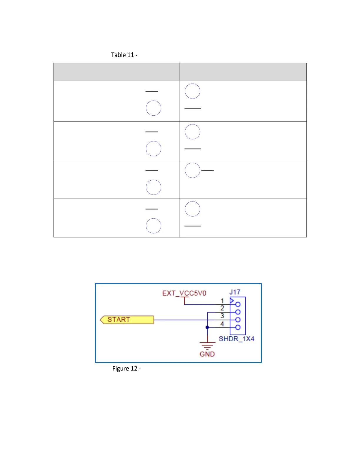
4.5.8 External Trigger Pinouts (Connector J17)
The following figure contains the pinout drawing for Connector J17 (External Trigger).
Connector J17 (External Trigger) Pinouts