Installation
1040-0011 Revision 34
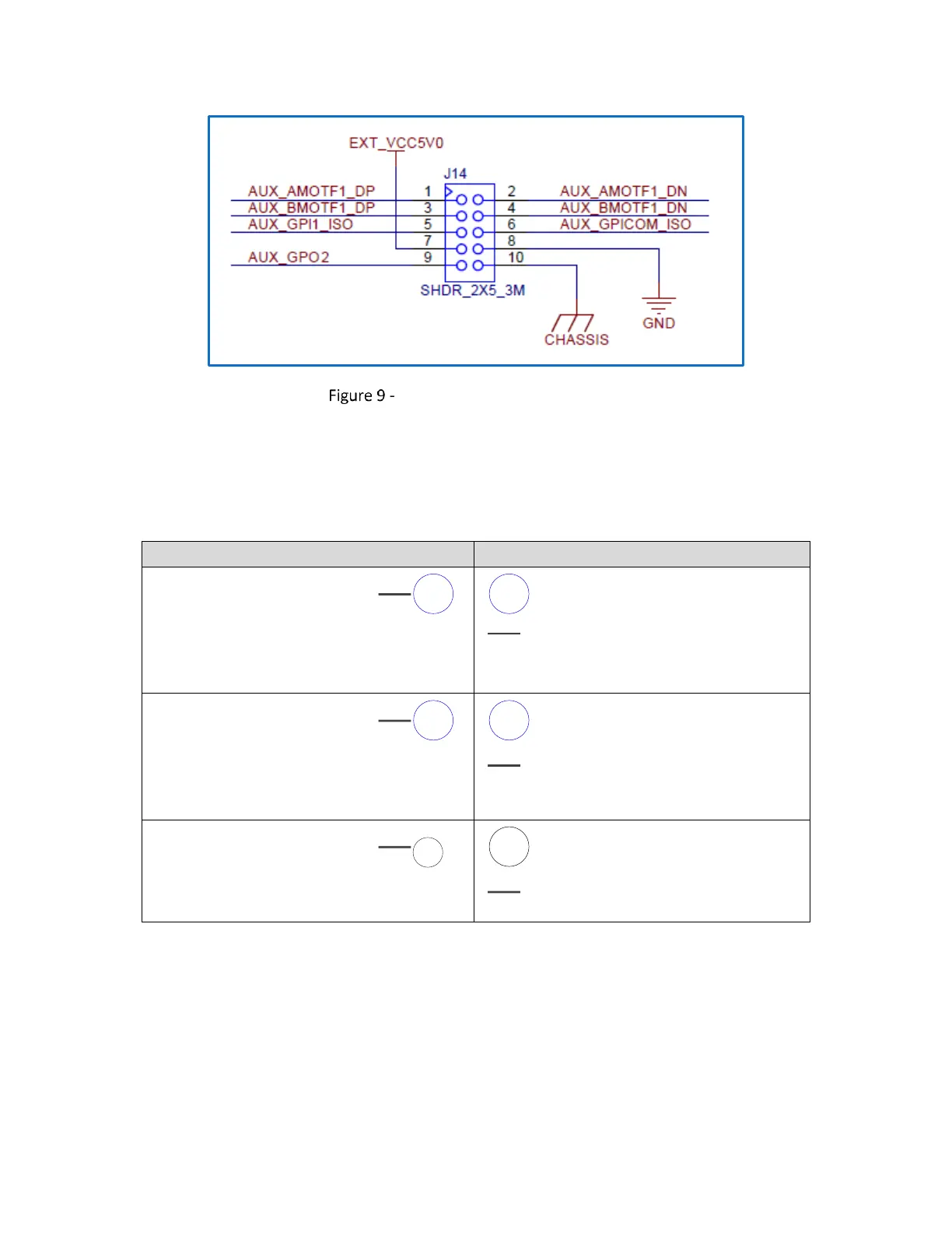
Connector J14 (MOTF-1) Pinouts
The following table contains a full description of the signal for each pin in the J14 Connector. These
signals are replicated from the Auxiliary I/O connector J13.
Connector J14 (MOTF-1) Signal Descriptions
Even-numbered Pins (2 – 10)
AUX_AMOTF1_DP
Secondary mark-on-the-fly
encoder input. Expected to be
connected to an RS-485 positive
“A” phase differential signal or a
5V TTL signal.
AUX_AMOTF1_DN
Secondary mark-on-the-fly encoder
input. Expected to be connected to
an RS-485 negative “A” phase
differential signal.
AUX_BMOTF1_DP
Secondary mark-on-the-fly
encoder input. Expected to be
connected to an RS-485 positive
“B” phase differential signal or a
5V TTL signal.
AUX_BMOTF1_DN
Secondary mark-on-the-fly encoder
input. Expected to be connected to
an RS-485 negative “B” phase
differential signal.
AUX_GPI1_ISO
External trigger input.
AUX_GPICOM_ISO
Isolator common for General
Purpose inputs