EasyManuals Logo

Novanta ScanMaster User Manual

Novanta ScanMaster
103 pages
To Next Page IconTo Next Page
To Previous Page IconTo Previous Page
Page #60 background imageLoading...
Page #60 background image
Installation
1040-0011 Revision 51
4.6.7 System Control Outputs and General Purpose Outputs J13 and J16
+24V
+5V
Internal System Control Signals
AUX_ERROR_READY_N
AUX_JOBACTIVE
AUX_BUSY
AUX_LASING
AUX_GPO{1-4}
8
From user connector J3
J13 & J16 Signals
X 8
1K
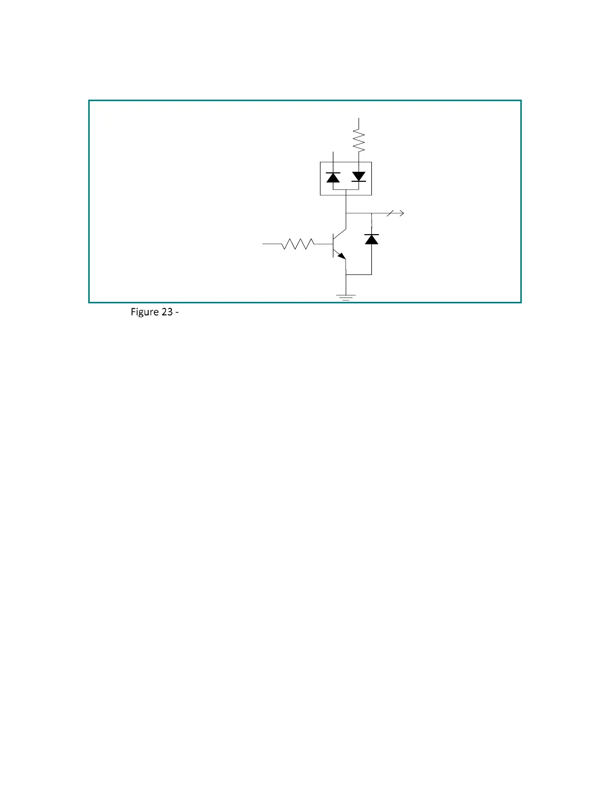
Signal Conditioning for System Control and General O/P (J13 & J16)
Note: These outputs are pulled up to +5V through a diode for convenience of driving lightly loaded
TTL devices. They are intended however to be used as sinking drivers where the load to be driven
has one end attached to 24V. The drivers will then switch the connected end of the load to ground.
The drivers can sink up to 500mA of current.

Table of Contents

Questions and Answers:

Question and Answer IconNeed help?

Do you have a question about the Novanta ScanMaster and is the answer not in the manual?

Novanta ScanMaster Specifications

General IconGeneral
BrandNovanta
ModelScanMaster
CategoryController
LanguageEnglish