Installation
1040-0011 Revision 40
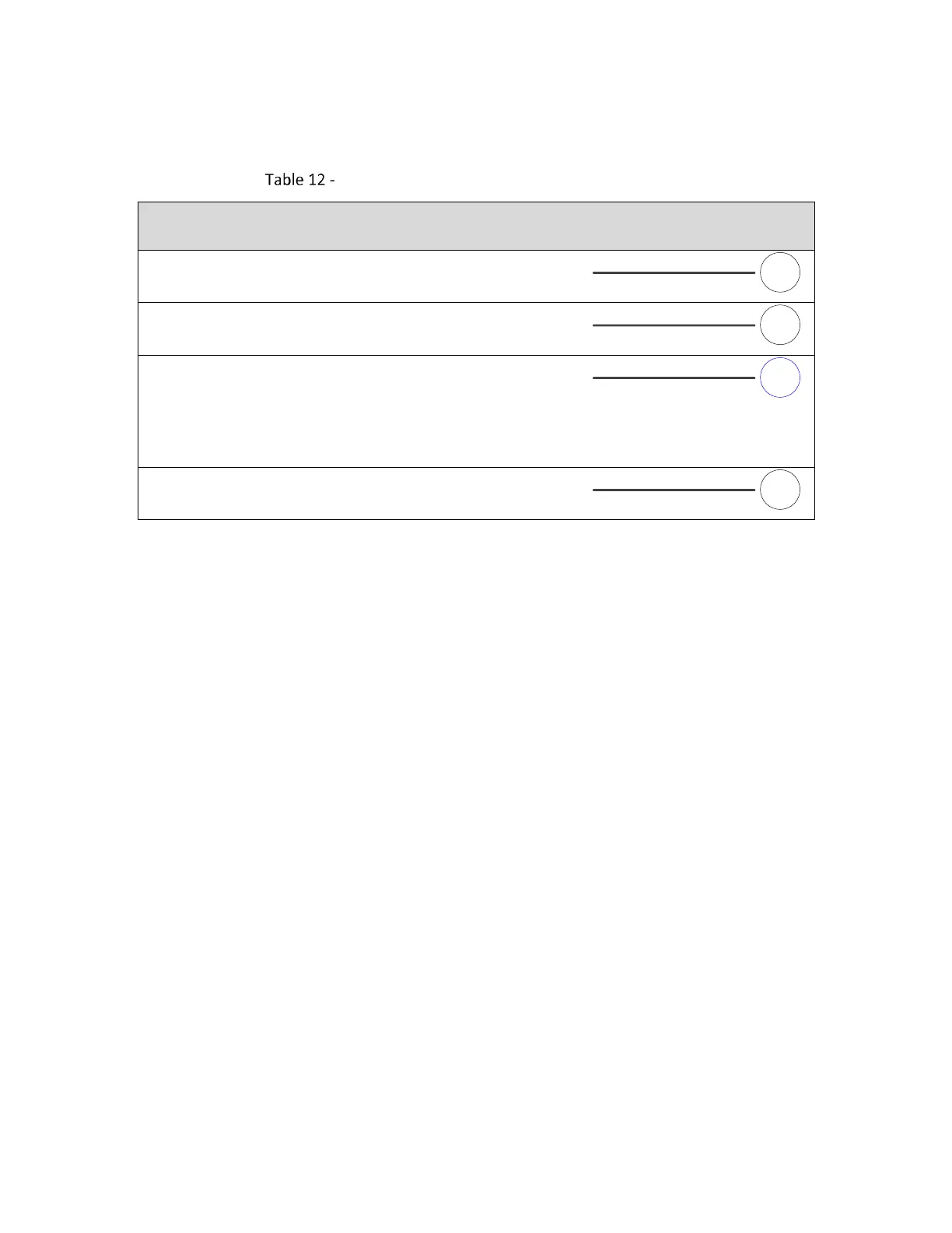
The following table contains a full description of the signal for each pin in the J17 Connector.
Connector J17 (External Trigger) Signal Descriptions
EXT_VCC5V0
5 Volts available for logic on customer board
GND
Digital ground reference
START
A marking job may contain an instruction that pauses execution
until this signal is asserted by external equipment.
Note: This function can also be achieved using the AUX_START
and AUX_START_ISO signals.
GND
Digital ground reference
4.5.9 Laser Signal Pinouts (Connector J18)
The following figure contains the pinout drawing for Connector J18 (Laser Signals).
Note: This connector uses ejectors to facilitate removal of an attached cable or laser adapter
module. Care must be taken during insertion to avoid damaging the ejectors.