Installation
1040-0011 Revision 28
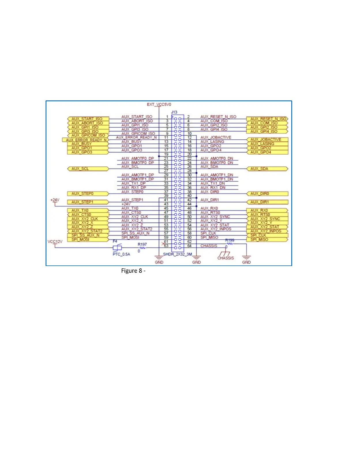
4.5.4 Auxiliary Signal Pinouts (Connector J13)
The following figure contains the pinout drawing for Connector J13 (Auxiliary).
Note: This connector uses ejectors to facilitate removal of an attached cable or module. Care must
be taken during insertion to avoid damaging the ejectors.
Connector J13 (Auxiliary) Pinouts
The following table contains a full description of the signal for each pin in the J13 Connector.