F3SG-SR/PG
63
Legislation and
Standards
Indicator
Indicator
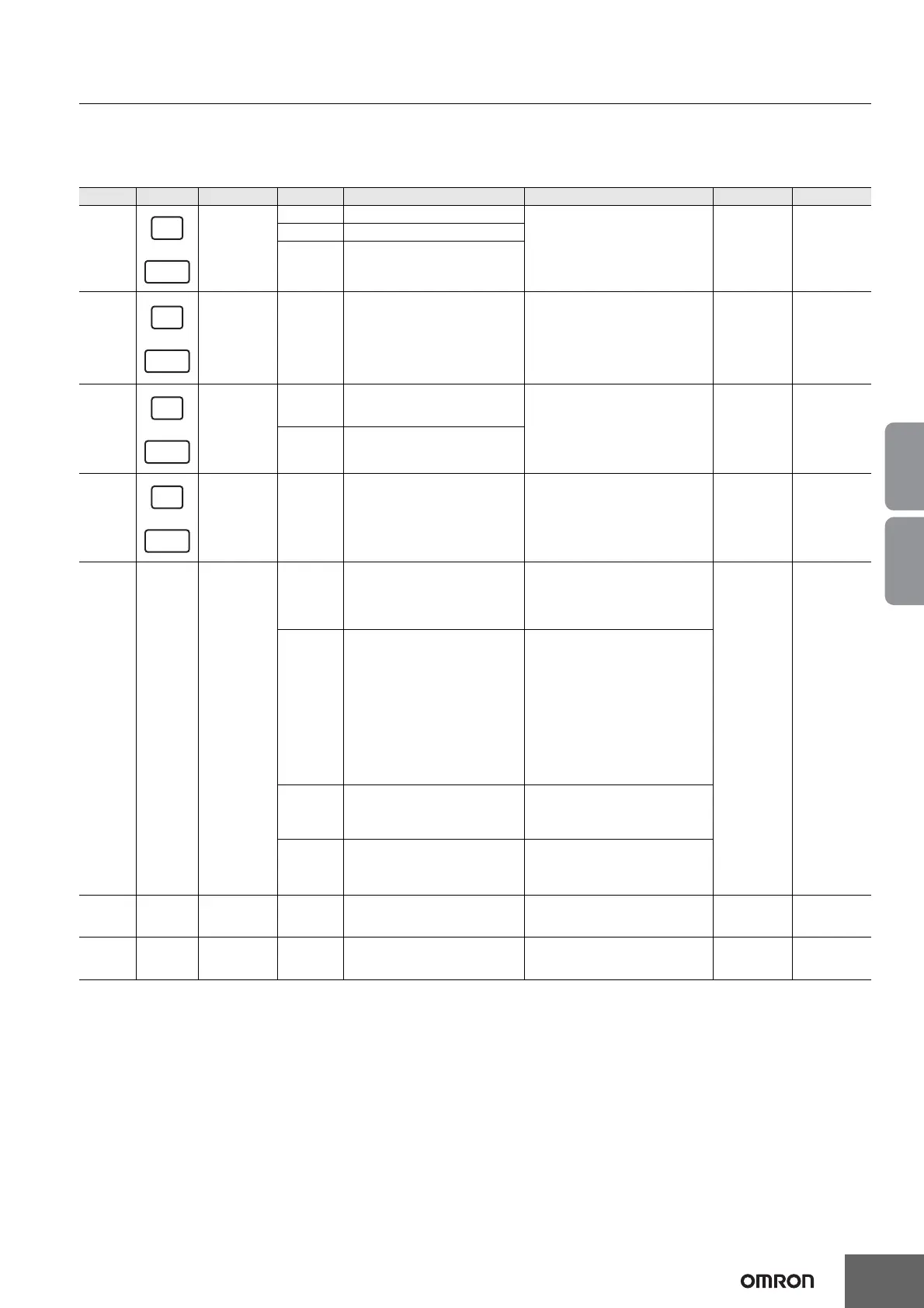
LED Indicators on F3SG-SR
Shown below are indication statuses of the LED indicators on the F3SG-SR when you purchased.
Emitter (F3SG-SR)
*1. The indicator of the emitter is illuminated only in the case the Wired Synchronization is enabled and is off in the case the Optical
Synchronization is enabled.
*2. Configurable by SD Manager 3.
*3. This is the case for the Standard Muting mode. For other muting modes, refer to User's Manual (Man.No.Z405).
*4. The Area Beam Indicator closer to the "TOP" mark on the F3SG-SR blinks.
*5. The Area Beam Indicator closer to the "BTM" mark on the F3SG-SR blinks.
*6. DIP switches is on the Intelligent Tap.
Location
Indicator
Name Color Illuminated Blinking F3SG-SRA F3SG-SRB
1 Scan code
Green Code A is selected
--- X X
Orange Code B is selected
OFF
Automatic interference prevention
by wired synchronization being
performed
2 Lockout Red
LOCKOUT state. The indicator is
illuminated in the emitter of another
sensor segment than that having a
lockout error (when in cascade
connection or between the emitter
and receiver in the Wired
Synchronization)
LOCKOUT state. The indicator is
illuminated in the emitter of a sensor
segment having a lockout error
XX
3
Operating
range
Green Long Mode is selected
LOCKOUT state due to Operating
range selection setting error
XX
OFF Short Mode is selected
4 Test Yellow --- External Test is being performed X X
5---
Area Beam
Indicator (ABI)
(*1)
Green
The target beams of the ABI are
unblocked and the safety outputs
are turned ON
MUTING or OVERRIDE state. In the
MUTING state, only the ABI
indicators in the muting zone are
blinking. Or the target beams of the
ABI are blocked instantaneously
X ---
Orange
Incident light level of the target
beams of the ABI is 170% (factory
default setting (*2)) or less of ON-
threshold (for 5 to 10 s)
Incident light level of the target beams
of the ABI is 170% (factory default
setting (*2)) or less of ON threshold
5 to 10 s after illuminated when
incident light level of the target beams
of the ABI is 170% (factory default
setting (*2)) or less of ON threshold.
Or one muting input becomes the ON
state and the MUTING state has not
been started yet, or one muting input
becomes the OFF state and the other
is not in the OFF state yet. (*3)
Red
The target beams of the ABI are
blocked
LOCKOUT state due to Cap error or
Other sensor error (*4), or Lockout
state due to DIP Switch setting error
(*5 *6)
OFF
The target beams of the ABI are
unblocked (The ABI then will be
illuminated in green when the safety
outputs are turned ON.)
---
6TOP
Top-beam-
state (*1)
Blue The top beam is unblocked
MUTING/OVERRIDE state, or
LOCKOUT state due to Cap error or
Other sensor error
--- X
7BTM
Bottom-beam-
state (*1)
Blue The bottom beam is unblocked
MUTING/OVERRIDE, or LOCKOUT
state due to DIP Switch setting error
(*6)
--
- X

 Loading...


