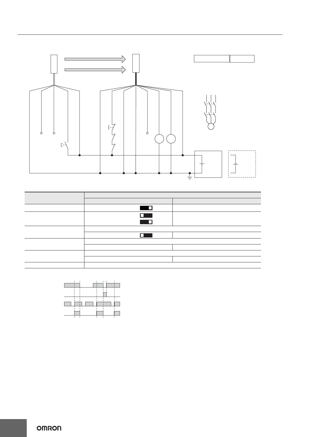
*1. Reverse the polarity of the power supply when using in the NPN system.
*2. Connect the line to 0 VDC if Operating Range Selection is used in Short
Mode.
*3. This is the case for a PELV circuit.
*4. Set the function with the DIP Switches on the Intelligent Tap or the SD
Manager 3, restore the settings to the F3SG-SR, and perform wiring
according to the wiring diagram.
*5.
This wiring example shows light emission stop when connected to 24 VDC with
PNP setting, and light emission stop when connected to 0 VDC with NPN
setting. If TEST switch is not needed, refer to the
User's Manual
(Man. No.
Z405).
: Indicates a switch position.
Function
Setting
DIP switch SD Manager 3
EDM *4 EDM Enabled [External device monitoring] : Enable
Interlock *4
Manual Reset (Start/
Restart Interlock)
[Start interlock] : Enable
[Restart interlock] : Enable
Operating Range Selection
Long : Open the OPERATING RANGE SELECT INPUT line of the emitter or connect the line to 24 VDC.
Long *4 [Operating Range Selection] : Long mode *4
Non-Muting system
Perform wiring according to the wiring diagram.
N/A [Muting] : Disable *4
External Test used
Connect the TEST line of the emitter to 24V/0V of the emitter via a test switch (NO contact).*5
N/A [External test signal inversion] : Disable
Optical Synchronization Do not connect the COM(+) and COM(-) lines of the of emitter and receiver with each other.

 Loading...


