F3SG-SR/PG
66
Connections (Basic Wiring Diagram)
F3SG-SR
Examples of a motor control system using the F3SG-SR are shown below. The examples are equivalent to up to PLe, Category 4 (ISO 13849-1).
Non-Muting System Wiring Examples
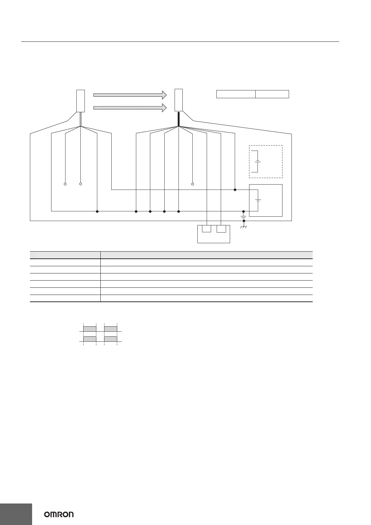
Auto Reset Mode with Optical Synchronization and EDM Unused
[Wiring Example]
Note: 1. Functional earth connection to the F3SG-SR housing is unnecessary when you use the F3SG-SR in a general industrial environment
where noise control or stable power supply is considered. However, when you use the F3SG-SR in an environment where there may be
excessive noise from surroundings or stable power supply may be interfered, it is recommended the F3SG-SR be connected to functional
earth.
2. The wiring examples in later pages do not indicate functional earth. To use functional earth, wire an earth cable according to the example
above. Refer to the User's Manual (Man.No.Z405) for more information.
Beam state: Unblocked
Blocked
OSSD
OSSD 1 (Black)
OSSD 2 (White)
24V/0V (Brown)
OPERATING RANGE
SELECT INPUT (Yellow)
*2
TEST (Black) *3
Not used (White)
24V/0V (Brown)
0V/24V (Blue)
0V/24V (Blue)
AUX (Red)
MUTE B (Pink)
MUTE A (Gray)
F39-JGC-L
F39-JGC-D
Timing chart
24 VDC
Wiring for NPN *1
*7
24 VDC
IN1
Safety controller
*5 *6
IN2
RESET/EDM
(Yellow)
*4
Receiver
Emitter
Intelligent Tap
Not needed
*1. Reverse the polarity of the power supply when using in the NPN system. Select a safety
controller of PNP or NPN type according to the system of your application.
*2. Connect the line to 0 VDC if Operating Range Selection is used in Short Mode.
*3. If External Test is used, refer to the User's Manual (Man.No.Z405).
*4. Connect the line to 24V/0V (brown) of the receiver via a lockout reset switch (NC contact) if
Lockout Reset is used.
*5. Refer to page 75 for more information.
*6. The safety controller and the F3SG-SR must share the power supply or be connected to the
common terminal of the power supply.
*7. This is the case for a PELV circuit.
Function Setting
EDM EDM Disabled (factory default setting)
Interlock Auto Reset (factory default setting)
Operating Range Selection Long : Open the OPERATING RANGE SELECT INPUT line of the emitter or connect the line to 24 VDC.
Non-Muting system Perform wiring according to the wiring diagram.
External Test not used Connect the TEST line of the emitter to 0V/24V of the emitter.
Optical Synchronization Do not connect the COM(+) and COM(-) lines of the of emitter and receiver with each other.

 Loading...


