F3SG-SR/PG
49
Ordering Information
Ratings and
Specifications
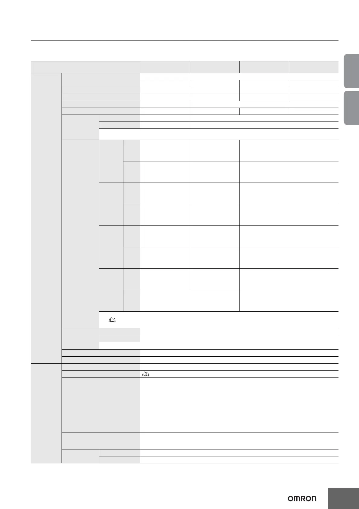
Ratings and Specifications
Safety Light Curtain F3SG-SR Series Main unit
The @@@@ in the model names indicate the protective heights in millimeters.
Model
F3SG-@SRA@@@@-14
F3SG-@SRB@@@@-14
F3SG-@SRA@@@@-25
F3SG-@SRB@@@@-25
F3SG-@SRA@@@@-45
F3SG-@SRB@@@@-45
F3SG-@SRA@@@@-85
F3SG-@SRB@@@@-85
Performance
Object resolution
(Detection capability)
Opaque objects
14-mm dia. 25-mm dia. 45-mm dia. 85-mm dia.
Beam gap 10 mm 20 mm 40 mm 80 mm
Number of beams 15 to 199 8 to 124 6 to 38 4 to 12
Lens size 4.4 × 3.4 mm (W × H) 6.7 × 4.5 mm (W × H)
Protective height 160 to 2,000 mm 160 to 2,480 mm 240 to 1,520 mm 280 to 920 mm
Operating range
Long 0.3 to 10.0 m * 0.3 to 20.0 m
Short 0.3 to 3.0 m * 0.3 to 7.0 m
* When operating at an ambient temperature of -10 to -30°C, use the F3SG-SR with the operating range of 0.3 to 5.0 m in Long
Mode and 0.3 to 1.5 m in Short Mode.
Response time
*1
Normal
mode
ON to
OFF
Optical synchronization:
8 to 18 ms
Wired synchronization:
10 to 21 ms
Optical synchronization:
8 to 13 ms
Wired synchronization:
10 to 17 ms
Optical synchronization: 8 ms
Wired synchronization: 10 ms
OFF to
ON
Optical synchronization:
40 to 90 ms
Wired synchronization:
50 to 105 ms
Optical synchronization:
40 to 65 ms
Wired synchronization:
50 to 85 ms
Optical synchronization: 40 ms
Wired synchronization: 50 ms
×2 Slow
mode *2
ON to
OFF
Optical synchronization:
16 to 36 ms
Wired synchronization:
20 to 42 ms
Optical synchronization:
16 to 26 ms
Wired synchronization:
20 to 34 ms
Optical synchronization: 16 ms
Wired synchronization: 20 ms
OFF to
ON
Optical synchronization:
80 to 180 ms
Wired synchronization:
100 to 210 ms
Optical synchronization:
80 to 130 ms
Wired synchronization:
100 to 170 ms
Optical synchronization: 80 ms
Wired synchronization: 100 ms
×4 Slow
mode *2
ON to
OFF
Optical synchronization:
32 to 72 ms
Wired synchronization:
40 to 84 ms
Optical synchronization:
32 to 52 ms
Wired synchronization:
40 to 68 ms
Optical synchronization: 32 ms
Wired synchronization: 40 ms
OFF to
ON
Optical synchronization:
160 to 360 ms
Wired synchronization:
200 to 420 ms
Optical synchronization:
160 to 260 ms
Wired synchronization:
200 to 340 ms
Optical synchronization: 160 ms
Wired synchronization: 200 ms
×8 Slow
mode *2
ON to
OFF
Optical synchronization:
64 to 144 ms
Wired synchronization:
80 to 168 ms
Optical synchronization:
64 to 104 ms
Wired synchronization:
80 to 136 ms
Optical synchronization: 64 ms
Wired synchronization: 80 ms
OFF to
ON
Optical synchronization:
320 to 720 ms
Wired synchronization:
400 to 840 ms
Optical synchronization:
320 to 520 ms
Wired synchronization:
400 to 680 ms
Optical synchronization: 320 ms
Wired synchronization: 400 ms
*1. Response time when used in one segment system.
Refer to page 55. Refer to the User's Manual (Man. No. Z405) for cascaded connection.
*2. Selectable by SD Manager 3.
Effective
aperture angle
(EAA)
(IEC 61496-2)
Type 4 ±2.5° max. *
Type 2 ±5.0° max. *
* Emitter and receiver at operating range of 3 m or greater.
Light source Infrared LEDs, Wavelength: 870 nm
Startup waiting time 3 s max.
Electrical
Power supply voltage (Vs) SELV/PELV 24 VDC±20% (ripple p-p 10% max.)
Current consumption Refer to page 55
Safety outputs (OSSD)
Two PNP or NPN transistor outputs (PNP or NPN is selectable by wiring of power supply.)
Load current: 300 mA max., Residual voltage: 2 V max. (except for voltage drop due to cable extension),
Capacitive load: 1 μF max., Inductive load: 2.2 H max. *1*2*3
Leakage current: 1 mA max.(PNP), 2 mA max.(NPN) *4
*1. For the F3SG-@SRA, the load current is 150 mA max. in 2-segment cascade and 80 mA max. in 3-
segment cascade.
*2. The residual voltage is 3 V max. when the Intelligent Tap is connected to the sensor.
*3. The load inductance is the maximum value when the safety output frequently repeats ON and OFF.
When you use the safety output at 4 Hz or less, the usable load inductance becomes larger.
*4. These values must be taken into consideration when connecting elements including a capacitive load
such as a capacitor.
Auxiliary output
One PNP or NPN transistor output (PNP or NPN is selectable by wiring of power supply.)
Load current: 100 mA max., Residual voltage: 2 V max. *
* The residual voltage is 3 V max. when the Intelligent Tap is connected to the sensor.
Output operation
mode
Safety output Light-ON (Safety outputs are turned to the ON state when the receiver receives an emitting signal.)
Auxiliary output Safety output (Inverted signal output: Enable) (default) (Configurable by SD Manager 3)

 Loading...


