24V/0V (Brown)
0V/24V (Blue)
Not used (Pink)
PSDI (Gray)
0V/24V (Blue)
Not used (White)
OPERATING RANGE
SELECT INPUT (Yellow)
*
2
TEST (Black)
24V/0V (Brown)
RESET/EDM
(Yellow)
AUX (Red)
OSSD 1 (Black)
OSSD 2 (White)
F39-JGC-L
F39-JG
C-D
24 VDC
Wiring for NPN
*
1
24 VDC
KM1
KM2
S2
S3
S1
0VDC
KM1 KM2
*
4
IN
PLC
*
3
KM1
KM2
M
Cam
S3
Receiver
Emitter
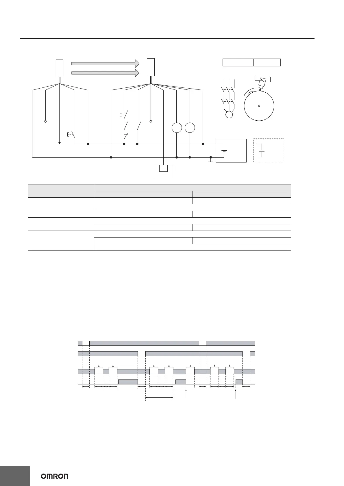
S1: Test switch
S2: Reset switch
S3: Press position switch
KM1, KM2: Safety relay with forcibly guided contacts (G7SA)
or magnetic contactor
PLC: Programmable logic controller (Used for monitoring only.
NOT related to safety system.)
M: Motor
Timing chart
Reset switch (S2)
Press position switch (S3)
OSSD
T1
min.
T2
min.
T4
min.
T5
min.
T5
min.
T2
min.
T3
min.
T4
min.
T3
min.
Dummy
break
T1
min.
T2
min.
T3
min.
T4
min.
T6
Machine stops Machine restarts
Feeding
parts
Feeding
parts
Removing
parts
Unintended
block
Dummy
break *
Dummy
break *
Unblocked
Blocked
T1: Minimum pressing time of reset switch. Configurable from 100 to 500 ms in 100-ms increments by SD Manager 3.
T2: Minimum break time (300 ms)
T3: Minimum unblocked time during the time from removing to feeding parts. T3 = T1
T4: Minimum break time (300 ms)
T5: Minimum pressing time of press position switch. T5 = T1
T6: Wait time until double break is complete (30 s or less)
* When the machine is stopped by unintended block in the middle of pressing of parts, operation of the reset switch (S1) and then double dummy
break are needed for reinitiation of the machine cycle.
Intelligent Tap
Needed
*
5
: Indicates a switch position.
Function
Setting
DIP switch SD Manager 3
EDM - [External device monitoring] : Enable *5
Operating Range Selection Short : Connect the OPERATING RANGE SELECT INPUT line of the emitter to 0 VDC.
PSDI N/A [PSDI] : Double break *5
Non-Muting system
Perform wiring according to the wiring diagram.
N/A [Muting] : Disable *5
External Test used
Connect the TEST line of the emitter to 24V/0V of the emitter via a test switch (NO contact). *6
N/A [External test signal inversion] : Disable
Optical Synchronization Do not connect the COM(+) and COM(-) lines of the of emitter and receiver with each other.
*1. Reverse the polarity of the power supply when using in the NPN
system. Select a PLC of PNP or NPN type according to the system
of your application.
*2. Open or connect the line to 24 VDC if Operating Range Selection is
used in Long Mode.
*3. When connecting to the PLC, the output mode must be changed with
the SD Manager 3 according to your application. For the setting this
function, refer to the User's Manual (Man.No.Z405).
*4. This is the case for a PELV circuit.
*5. Set the function with the SD Manager 3, restore the settings to the
F3SG-SR, and perform wiring according to the wiring diagram.
*6. This wiring example shows light emission stop when connected to
24 VDC with PNP setting, and light emission stop when connected to
0 VDC with NPN setting. If TEST switch is not needed, refer to the
User's Manual (Man. No. Z405).

 Loading...


