F3SG-SR/PG
94
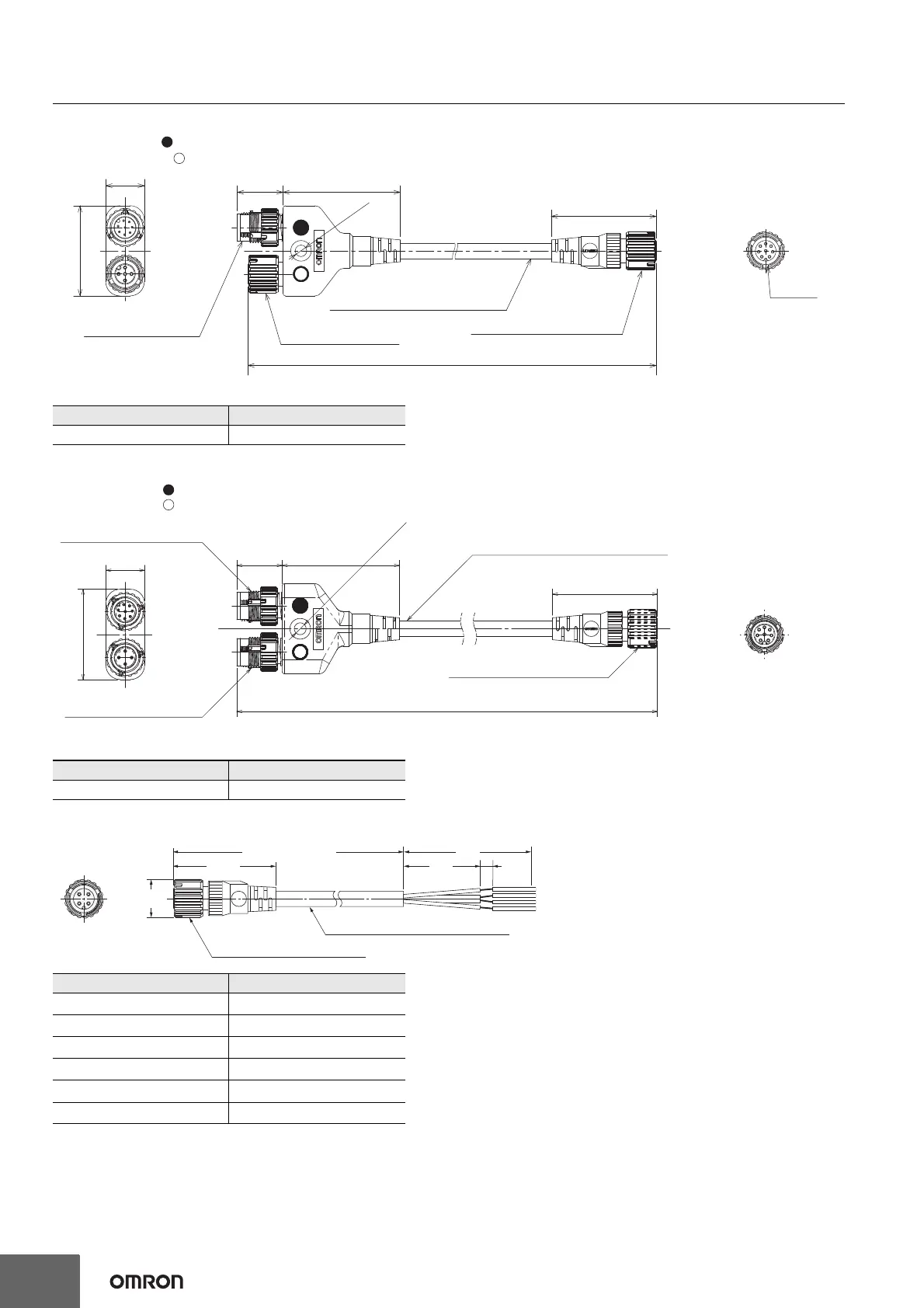
Y-Joint Plug/Socket Connector (F39-GCNY2, sold separately)
Reset Switch Connector (F39-GCNY3, sold separately)
Connector Connected to Cable, Socket on One Cable End (XS5F-D421-@80-F, sold separately)
Model Length
F39-GCNY2 0.5 m
Model Length
F39-GCNY3 0.5 m
Model Length (L)
XS5F-D421-C80-F 1 m
XS5F-D421-D80-F 2 m
XS5F-D421-E80-F 3 m
XS5F-D421-G80-F 5 m
XS5F-D421-J80-F 10 m
XS5F-D421-L80-F 20 m
17.7 45.5
40.7
15.0
35.0
M12 x 1
4.6 dia.
To control
panel side
To emitter
M12 IP67 connector,
8-wire
M12 IP67 connector,
5-wire
M12 IP67 connector, 8-wire
Insulated vinyl round cable, dia. 6
minimum bending radius R36
To receiver
Material: PBT (Main body)
Plug marked with (blue circle): Connect to control panel side
Socket marked with (open circle): Connect to emitter
Material: PBT (Main body)
CN1
CN3
To receiver
CN2
To control
panel side
To reset
switch side
Plug marked with (blue circle): Connect to control panel side
Plug marked with (open circle): Connect to reset switch side
17.6 45.5
4.6 dia.
35.0
15.0
40.7
500
M12 IP67 connector, 8-wire
Insulated vinyl round cable, dia. 6
minimum bending radius R36
M12 IP67 connector, 4-wire
M12 IP67 connector, 8-wire
50
5
30
14.9 dia.
40.7
L (Cable length)
Insulated vinyl round cable dia. 6
M12 IP67 connector, 4-wire

 Loading...


