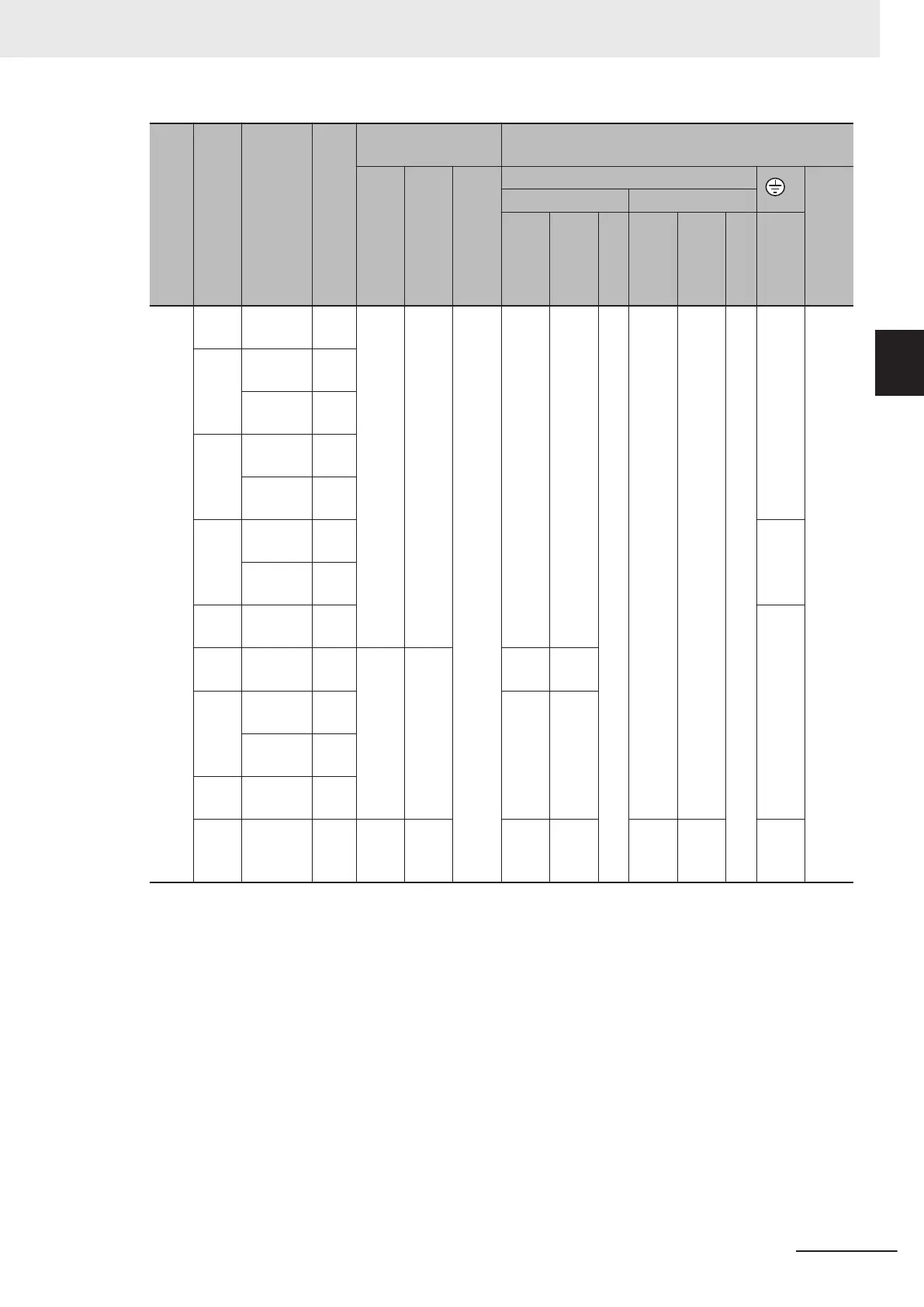
Power supply
system
Standard applicable
motor (kW)
Inverter Model
HHD/HD/HND/ND
modes
Tightening torque
lb-in (N・m)
Wire size AWG (mm
2
)
Main Terminal
Inverter's
grounding
Control circuit
auxiliary input
Main circuit copper wire
G
Control circuit
auxiliary input
L1/R, L2/S, L3/T U, V, W
60°C Cu Wire
75°C Cu Wire
Remarks
60°C Cu Wire
75°C Cu Wire
Remarks
Inverter's
grounding
Sin-
gle-
phas
e
200
V
0.1 3G3M1-
AB001
HHD 7.1
(0.8)
10.6
(1.2)
- 14
(2.1)
14
(2.1)
*3
14
(2.1)
14
(2.1)
*3
14
(2.1)
-
0.2 3G3M1-
AB001
HND
3G3M1-
AB002
HHD
0.4 3G3M1-
AB002
HND
3G3M1-
AB004
HHD
0.75 3G3M1-
AB004
HND 12
(3.3)
3G3M1-
AB007
HHD
1.1 3G3M1-
AB007
HND 10
(5.3)
1.5 3G3M1-
AB015
HHD 10.6
(1.2)
15.9
(1.8)
12
(3.3)
12
(3.3)
2.2 3G3M1-
AB015
HND 10
(5.3)
10
(5.3)
3G3M1-
AB022
HHD
3 3G3M1-
AB022
HND
3.7 3G3M1-
AB037
HHD 27
(3)
27
(3)
6
(13.3
)
8
(8.4)
12
(3.3)
12
(3.3)
8
(8.4)
*1. Wires can be connected without any terminal treatment.
*2. Only 75°C (167°F) Cu wiring can be used.
*3. Shows common wiring sizes for UL Open Type and Enclosed Type. Please contact us separately if dedicat-
ed UL Open Type wiring sizes are required.
2 Design
2-81
M1 Series Standard Type User's Manual (I669)
2-4 Others
2
2-4-3 UL/cUL Standards Cautions

 Loading...


