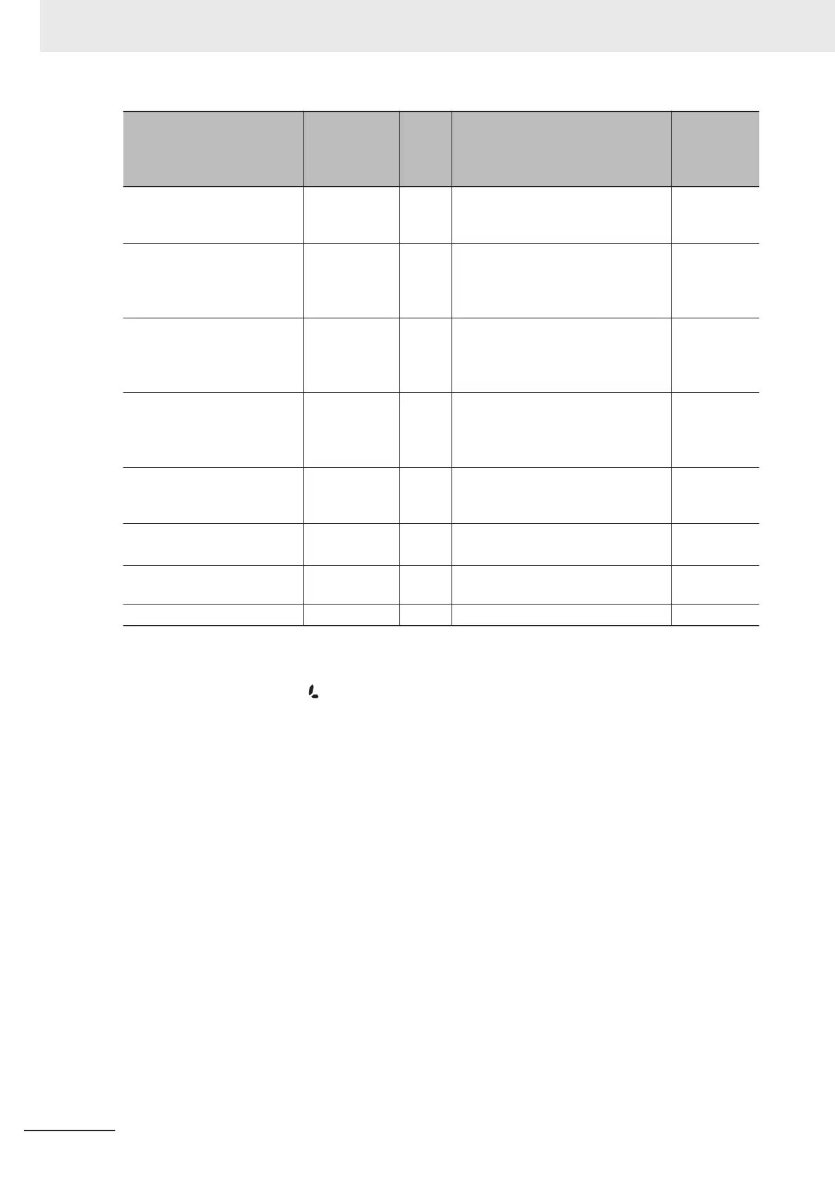
Monitor item
Unit LED dis-
play
□ Not lit
■ Lit
Unit Outline of display value
Function
code
E43 data
Analog input monitor
*7
□Hz □A -
The analog input of the inverter is
displayed after conversion to the de-
sired display
17
Current position
*10
□Hz □A -
The upper four digits and lower four
digits of the current position user val-
ue (hexadecimal) are displayed al-
ternately
21
Position error
*10
□Hz □A -
The upper four digits (signed) and
lower four digits of the position devi-
ation user value (hexadecimal) are
displayed alternately
22
Target position
*10
□Hz □A -
The upper four digits (signed) and
lower four digits of the target position
user value (hexadecimal) are dis-
played alternately
28
Torque current
*8
□Hz □A %
The torque current command value
or torque current calculated value is
displayed
23
Magnetic flux command val-
ue
*8
□Hz □A %
The magnetic flux command value is
displayed
24
Input watt-hour
□Hz □A kWh
Display value = Input watt-hour
(kWh)/100
25
Torque bias □Hz □A % The torque bias value is displayed 30
*1. 100% is the motor rated torque.
*2. In the output voltage display, V is displayed at the lowermost digit of the LED monitor in place of unit symbol
V (volt).
*3.
In the load rate display, the icon is displayed at the lowermost digit of the LED monitor in place of %.
*4. Displayed only when performing PID control (J01=1, 2 or 3).
*5. The dot at the lowermost digit of the LED monitor flashes in the PID process command/PID output display.
*6. The dot at the lowermost digit of the LED monitor lights in the PID feedback value display.
*7. The analog input monitor is displayed only when the analog input monitor for display is set to enabled at
E61 to E63 terminal function selection. The value converted by Input T
erminal [AI1] Analog Input Adjustment
Maximum Scale (C59), Input T
erminal [AI1] Analog Input Adjustment Minimum Scale (C60), Input Terminal
[AI2] Analog Input Adjustment Maximum Scale (AII) (C65), Input Terminal [AI2] Analog Input Adjustment
Minimum Scale (AII) (C66), Input T
erminal [AI2] Analog Input Adjustment Maximum Scale (AIV) (C71) and
Input Terminal [AI2] Analog Input Adjustment Minimum Scale (AIV) (C72) is displayed.
*8. 0 (zero) is displayed during V/f control.
*9. Only (C21=3) is displayed when performing timed operation.
*10. Displayed when the position control function is enabled.
Select the monitor information to be displayed on the Digital Operator LED when the inverter is stop-
ped. When “0: Set frequency display” is set at Operator Display when Stopped Selection (E44), the set
frequency is displayed, and when “1: Output frequency display” is set, the output frequency is dis-
played.
The display format is that selected at Operator Display Speed Monitor Item Selection (E48).
3 Operation and Test Run
3-6
M1 Series Standard Type User's Manual (I669)
 Loading...


