Parameter
No.
Function name Monitor or Data Range
Default
data
Setting
during
RUN
Unit
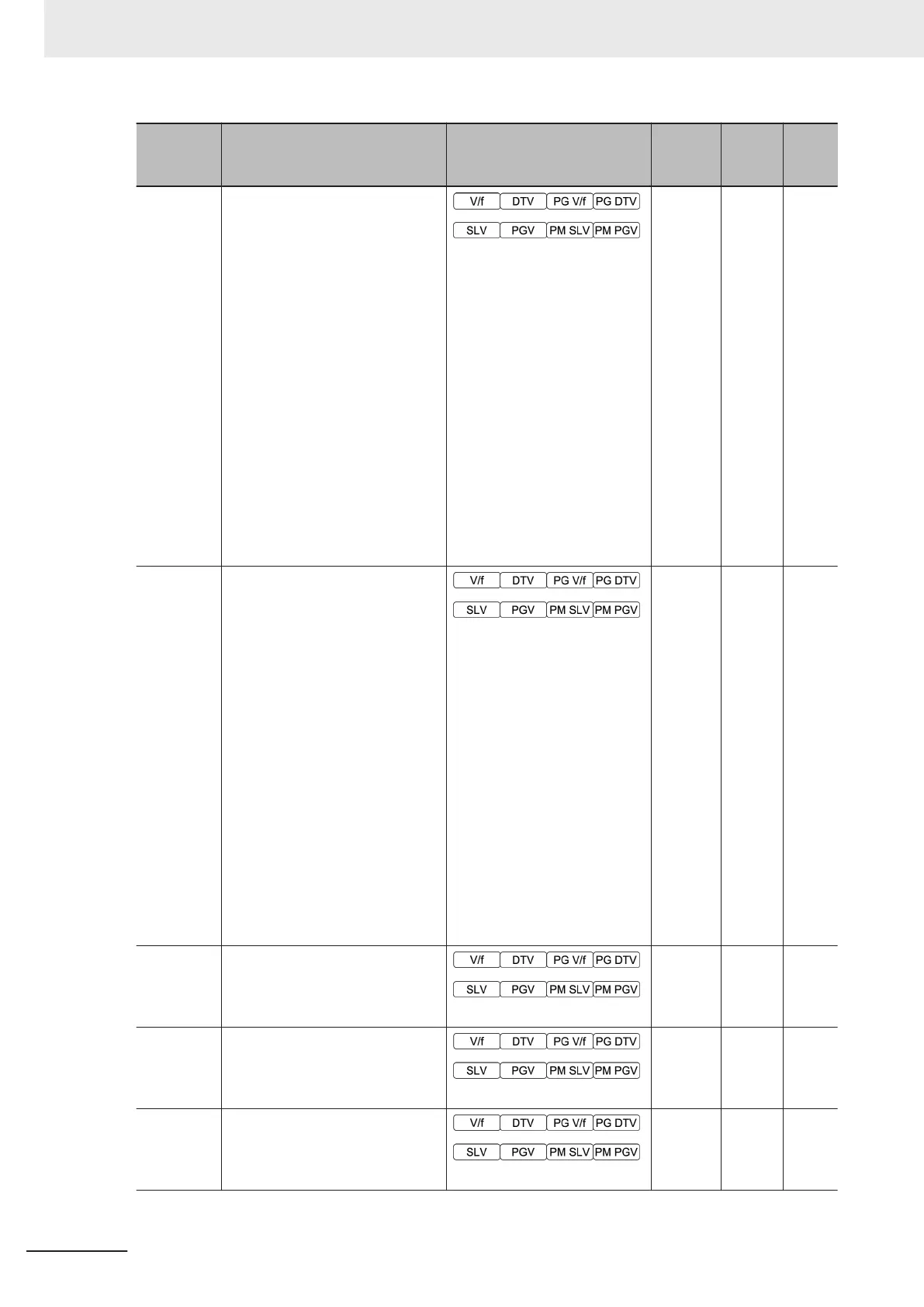
W42
Communications Input Signal
Monitor
Bit15: RST
Bit14: DI7
Bit13: DI6
Bit12: ---
Bit11: ---
Bit10: ---
Bit9: ---
Bit8: ---
Bit7: ---
Bit6: DI5
Bit5: DI4
Bit4: DI3
Bit3: DI2
Bit2: DI1
Bit1: REV
Bit0: FWD
0 -
-
W43
Communications Control Output
Signal Monitor
Bit15: ---
Bit14: ---
Bit13: ---
Bit12: ---
Bit11: ---
Bit10: ---
Bit9: ---
Bit8: RO
Bit7: ---
Bit6: ---
Bit5: ---
Bit4: ---
Bit3: ---
Bit2: ---
Bit1: DO2
Bit0: DO1
0 - -
W44 Input Terminal [AI1] Input Voltage
-12.0 to 12.0
0 - V
W45
Input Terminal [AI2]AII Input Cur-
rent (AII)
0.0 to 30.0 mA
0 - mA
W46
Output Terminal [AO]AOV Output
Voltage
-0.0 to 12.0 V
0 - V
4 Parameter List
4-34
M1 Series Standard Type User's Manual (I669)
 Loading...


