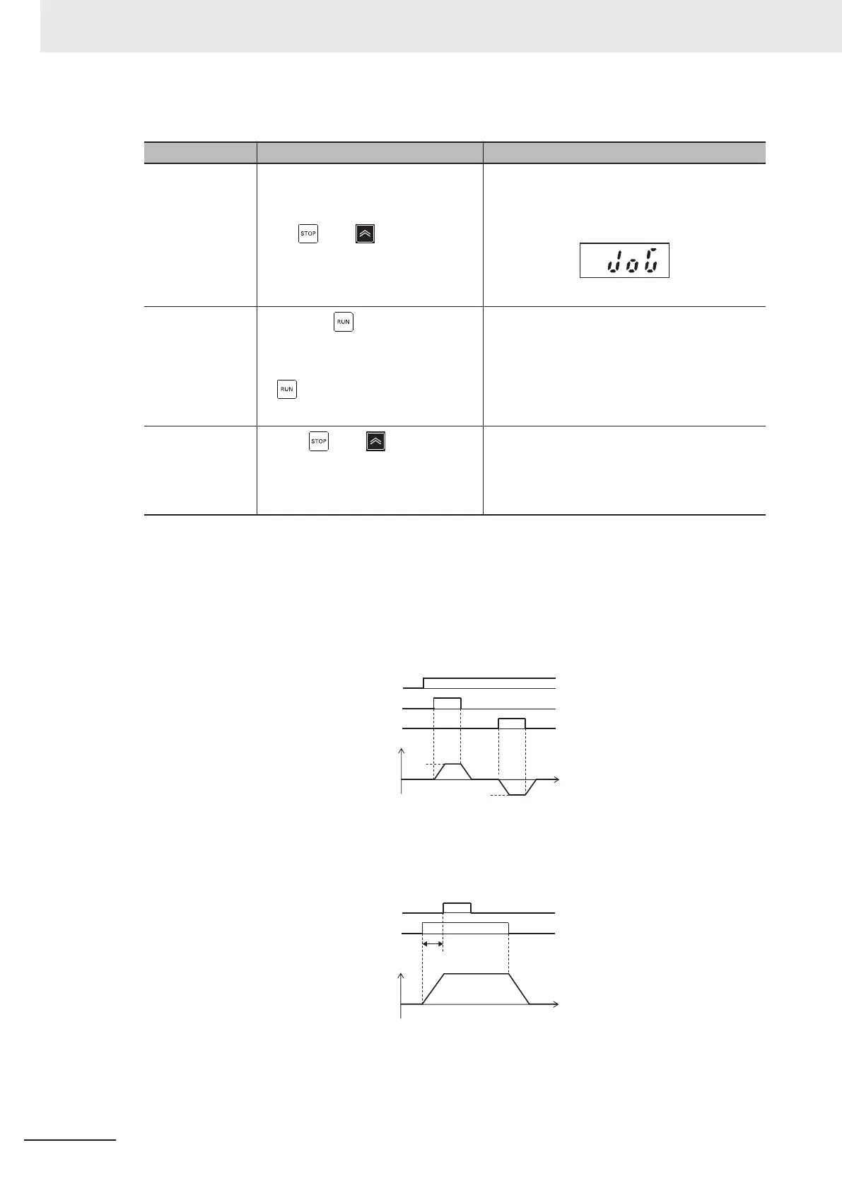
Jogging function via Operator and RUN command
Operation Display on Operator
Step 1
• While the operation mode is set to
the RUN mode (refer to 3-1-2 Key
Operation Method on page 3-3), if
the
key + key on the Oper-
ator are pressed simultaneously
during a stop, jogging operation is
performed.
The jogging frequency is displayed on the LED
monitor for approximately one second, and the
screen returns to the jog display.
Step 2
• While the
key on the touch
panel is held down, jogging opera-
tion is performed, and when the
key is released, a deceleration
stop is performed.
Step 3
• If the key + key on the Op-
erator are pressed during jogging
operation, the jogging operation
enabled state is canceled.
Disabled in operation (when Jogging Operation Selection (E111) = “0,”
“1,” “2”)
• Turn the JG terminal ON and then turn the FW or RV terminal ON.
•
During operation (FW terminal is ON, R
V terminal is ON), the jogging function is disabled. Note,
however
, that the function is enabled within 100 ms of starting operation. During operation, the
jogging operation is enabled, and jogging operation is started.
C20
H54 H55
H54 H55
-C20
Output
frequency
JG
F
W
RV
• Jogging operation is not performed if the JG signal turns ON after the FW signal turns ON first
and 100 ms or more elapses. To perform jogging operation, turn the JG terminal ON and then
turn the FW or RV terminal ON.
Fig.: Operation of setting when disabled while inverter is running
JG
FW
Normal operation
100 ms or
more elapsed
Output
frequency
5 Basic Settings
5-62
M1 Series Standard Type User's Manual (I669)
 Loading...


