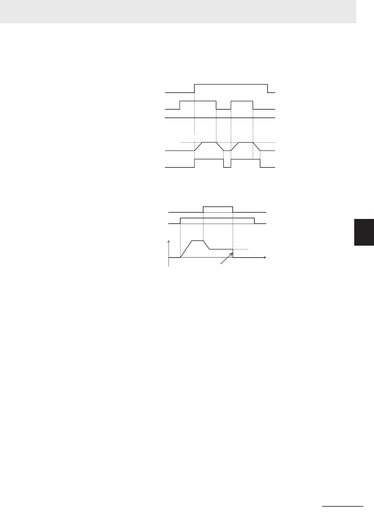
Enabled in operation (when Jogging Operation Selection (E111) = “3,” “4,”
“5”)
• Jogging is performed even if the FW signal turns ON first.
Output frequency
Jogging Frequency (C20)
Output gate
Frequency
Reference
0 Hz
JG
FW
H54 H55 H55H54
Fig.: Jogging operation switching while inverter is running
However, if the JG signal turns OFF first, the motor comes to a free-run state.
Fig.: Operation when jogging is canceled
H55
C20
JG
FW
Normal
operat
io
n
Output
f
r
equenc
y
Free-run
If the JG signal is turned ON again with the motor in a free-run state (JG signal OFF and FW signal
ON), jogging operation is started again.
If the FW signal is turned OFF with the motor in a free-run state (JG signal OFF and FW signal
ON), and the FW signal is turned ON again, normal operation is performed.
Relationship with DC braking
When the jogging function is used to perform inching, the inverter sometimes does not come to an
exact stop in applications such as turntables and rotates an extra bit more before it comes to a
stop.
In vector control, the braking torque just before the stop can be adjusted so that the inverter comes
to an exact stop by adjusting the speed adjuster (ASR). However, in V/f control, sufficient braking
torque sometimes cannot be ensured simply by adjusting the torque boost.
In cases like these, jogging operation and the DC braking function are used in combination to ad-
just inching.
For details on DC braking, refer to 7-5-1 DC Injection Braking (DB) on page
7-63.
Operation when the RUN command is turned OFF during jog operation with the DB (DC braking)
terminal turned ON is as follows.
(Example: When External DC Injection Braking Edge/Level Selection (E115) = “1: Level operation”)
• When E111 = 0, 3, operation immediately becomes free run when the RUN command turns OFF,
and immediately DC braking by the DB terminal operates.
5 Basic Settings
5-63
M1 Series Standard Type User's Manual (I669)
5-9 Multi-function Input
5
5-9-1 Input Terminal Functions
 Loading...