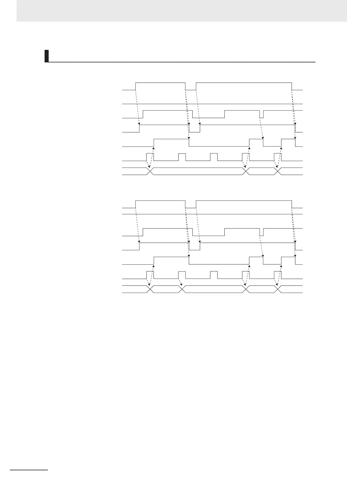
Operation Sequence
For Cont = 0: Trigger First Event Mode (First Trigger)
Touch probe signal
Previous value Touch probe position A
Touch probe
position B
Touch probe
position C
Touch probe position 1 (Positive)
/Touch probe position 2 (Positive)
Touch probe function
bit 0 / bit 8
Ena bit
Touch probe function
bit 1 / bit 9
Cont bit
Touch probe function
bit 4 / bit 12
Eps bit
Touch probe status
bit 0 / bit 8
Enb bit
Touch probe status
bit 1 / bit 9
Plc bit
For Cont = 1: Continuous Mode (Continuous)
Touch probe signal
Previous value Touch probe position B
Touch probe
position A
Touch probe
position C
Touch probe
position D
Touch probe position 1 (Positive)
/Touch probe position 2 (Positive)
Touch probe function
bit 0 / bit 8
Touch probe function
bit 1 / bit 9
Touch probe function
bit 4 / bit 12
Touch probe status
bit 0 / bit 8
Touch probe status
bit 1 / bit 9
Ena bit
Cont bit
Eps bit
Enb bit
Plc bit
6 Vector Control and Applied Functions
6-64
M1 Series Standard Type User's Manual (I669)

 Loading...


