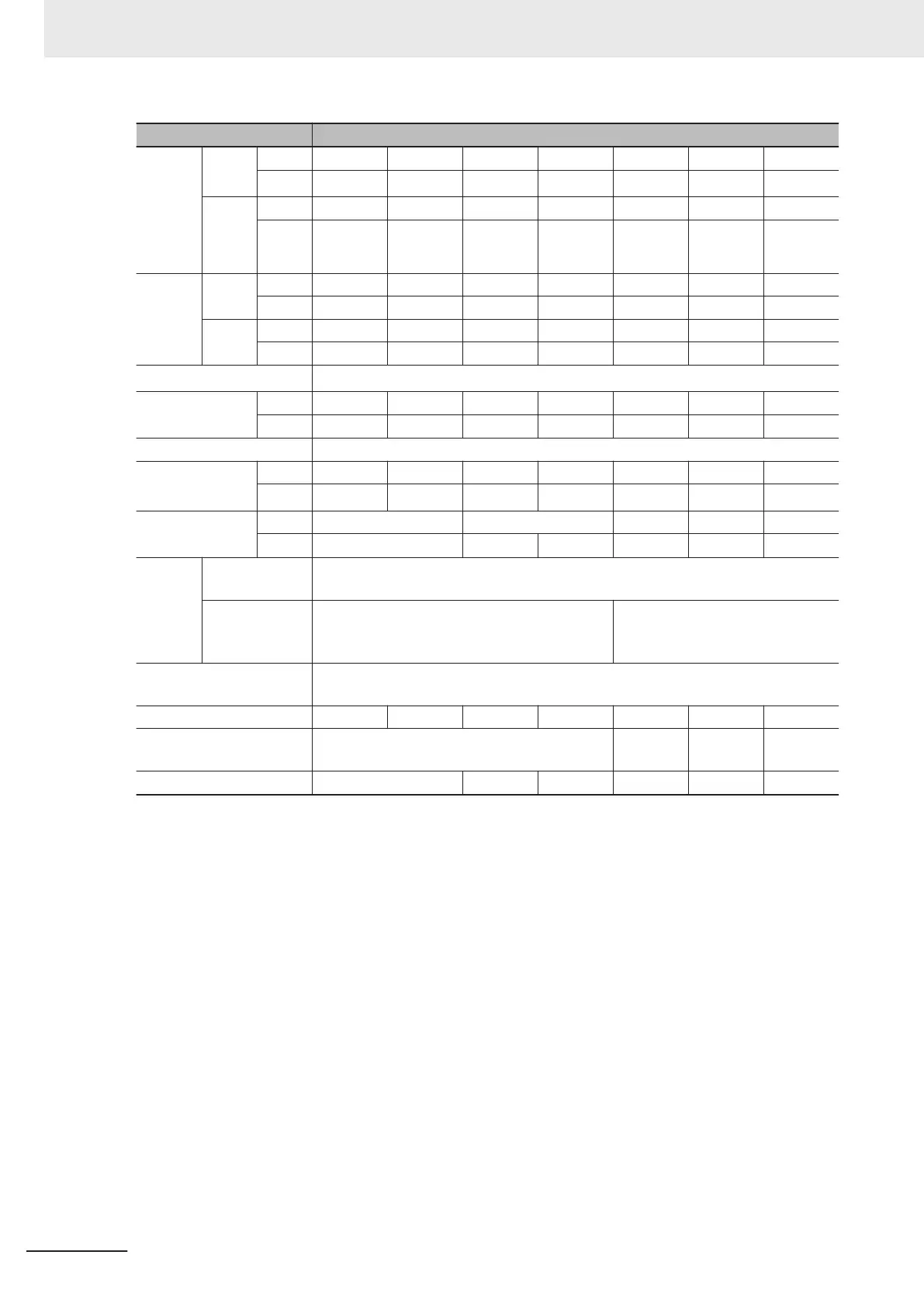
Item Single-phase 200 V
Maxi-
mum
applica-
ble mo-
tor ca-
pacity
*1
kW HHD 0.1 0.2 0.4 0.75 1.5 2.2 3.7
HND
0.2 0.4 0.55 1.1
2
*8
2.7
*9
-
HP HHD 1/8 1/4 1/2 1 2 3 5
HND
1/4 1/2 3/4 1 1/2 3 4 -
Rated
output
capacity
[kV
A]
*2
200 V HHD
0.3 0.6 1 1.7 2.8 3.8 6.1
HND 0.4 0.7 1.2 2.1 3.3 4.2 -
240 V HHD 0.4 0.7 1.2 2.1 3.3 4.6 7.3
HND 0.5 0.8 1.5 2.5 4 5 -
Rated input voltage
*3
Single-phase 200 to 240 V, 50/60 Hz
Rated input cur-
rent [A]
*4
HHD 1.8 3.3 5.4 9.7 16.4 22 45.4
HND
3.3 4.9 7.3 13.8 20.2 26 -
Rated output voltage Single-phase 200 to 240 V (with AVR)
Rated output cur-
rent [A]
*5
HHD 1 1.6 3 5 8 11 17.5
HND
1.2 1.9
3.5
*7
6.0
*7
9.6
*7
12
*7
-
Braking torque
[%]
*6
HHD 150 100 70 40 40
HND
75 73 68 48 29 -
Braking
resistor
circuit
Regenerative
braking
Built-in braking resistor circuit (discharge resistor separately mounted)
Minimum con-
nection resist-
ance [
Ω]
100 to 120 40 to 120
Short circuit current rating
[kA]
100
Weight [kg] 0.5
0.5 0.6 0.9 1.4 1.7 3.8
Dimensions (Width ×
Height) [mm]
68×127 110×130 140×130 180×220
Dimensions (Depth) [mm] 98 120 165 166 156 171
*1. The maximum applicable motor capacity is given for a standard four-phase motor. When selecting an inver-
ter, select not just by kW but also ensure that the inverter rated output current is greater than the motor rat-
ed current.
*2. In calculating the rated capacity
, the rated output voltage is assumed to be 200 V or 240 V.
*3. A voltage higher than the power supply voltage cannot be output.
*4. When Carrier Frequency (F26) is set to the following or below, derating is required.
HHD mode...AB001 to A2037: 8 kHz
HND mode...AB001 to A2022: 4 kHz
For derating, refer to A-1 Derating Table on page A-2.
*5.
The following shows the calculated value when the power supply capacity is 500 kVA (10x the inverter ca-
pacity when the inverter capacity exceeds 50 kVA) and when a %X = 5% power supply is connected.
*6. The numeric value is the average braking torque per individual motor. (Varies according to motor efficiency)
*7. Allowable ambient temperature of 40°C or below of AB004, AB007, AB015 and AB022.
The rated output current in the HND mode decreases by 2% for every temperature increase of 1°C when
the ambient temperature is 40°C or more.
*8. The maximum applicable motor capacity is 2.2 kW when the input voltage is 220 to 240 V.
*9. The maximum applicable motor capacity is 3.0 kW when the input voltage is 220 to 240 V.
1 Overview
1-14
M1 Series Standard Type User's Manual (I669)

 Loading...


