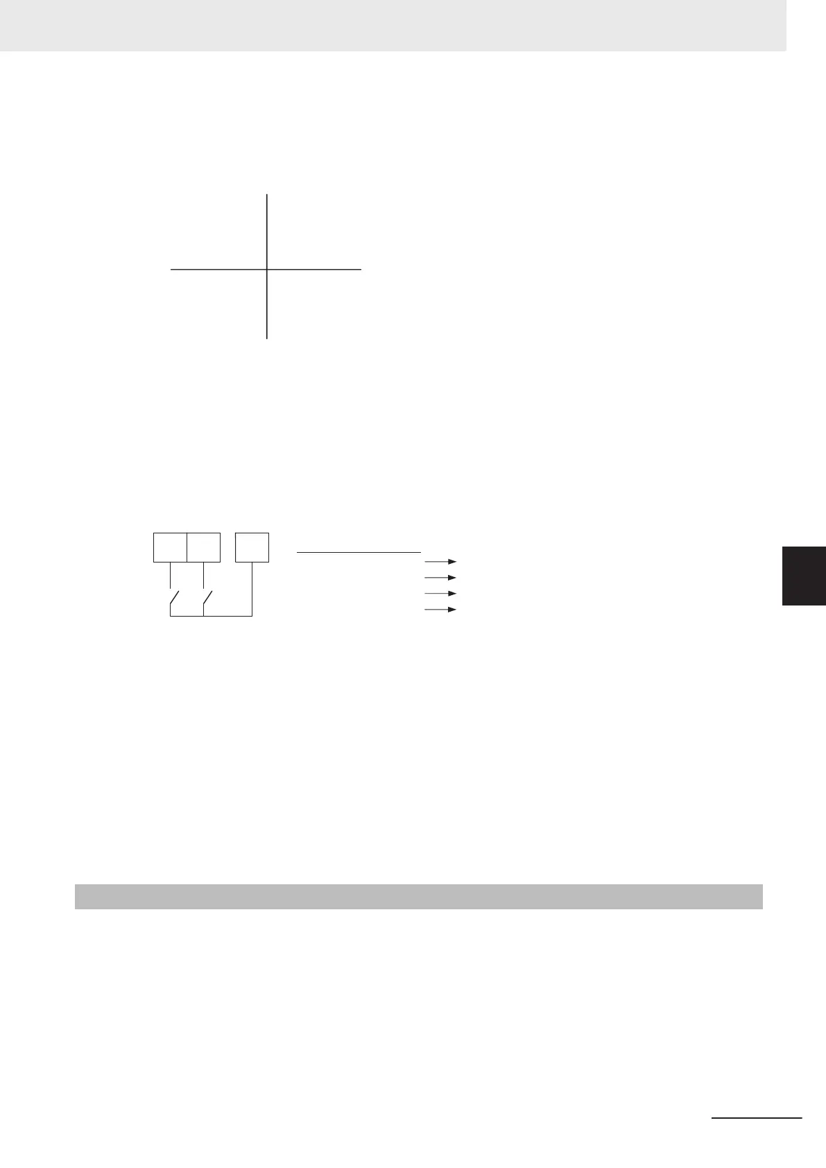
Details of Four Quadrant Independent (H75 = 0)
The torque limit when “0: Four quadrant independent” is selected at Torque Limit Operation Selec-
tion (H75) (F40, F41, E16 and E17) is as shown in the figure below.
Torque
2nd quadrant
3rd quadrant
1st quadrant
4th quadrant
(Forward)
(Reverse)
Power running
F40
Power running
E16
Regeneration
E17
Regeneration
F41
Details of Four Quadrant Identical (H75 = 1)
When “1: Four quadrants identical” is selected at Torque Limit Operation Selection (H75), the tor-
que limit value (F40, F41, E16 and E17) that is switched by torque limit switching 1 and 2 allocated
to multifunction input terminals is set as shown in the figure below.
Exam-
ple)
When torque limit switching 1 (14: TRQ1) is allocated to multifunction input terminal DI1 and tor-
que limit switching 2 (185: TRQ2) is allocated to multifunction input terminal DI2
DI2DI1
185
14
DIC
14: TRQ1 185: TRQ2
OFF
ON
OFF
ON
OFF
OFF
ON
ON
F40
F41
E16
E17
Details of Torque Limiter (H74 = 0)
This parameter limits the torque to a fixed value.
Details of Frequency Rising Limit for Torque Limit (H76)
When a load is applied on the regeneration side, the actual speed of the motor is pulled to the load
side to become faster than the output frequency of the inverter. When this state continues, the volt-
age at both ends of the main circuit capacity rises, and an overvoltage is detected and results in
the inverter tripping. To avoid a trip, the overvoltage is averted by increasing the output frequency
to more than the actual frequency reference. However
, at this time, this torque limiter functions to
apply a limit to how far the frequency rises.
6-11-2
Torque Monitor
In the torque calculation value of V/f control and the torque command value in vector control, the tor-
que polarity is generally + for drive and - for braking. When the rotational direction changes from for-
ward rotation to reverse rotation in elevator loads or similar applications, the polarity also is reversed
as torque changes from drive to braking.
When Sysmac Studio is connected to trace torque data, continuous data can no longer be acquired as
the polity of the torque command value also changes interlocked with the speed polarity. The continui-
ty of torque data can be ensured as forward drive and reverse braking is handled as + polarity and
6 Vector Control and Applied Functions
6-83
M1 Series Standard Type User's Manual (I669)
6-11 Torque Limit Function
6
6-11-2 Torque Monitor

 Loading...