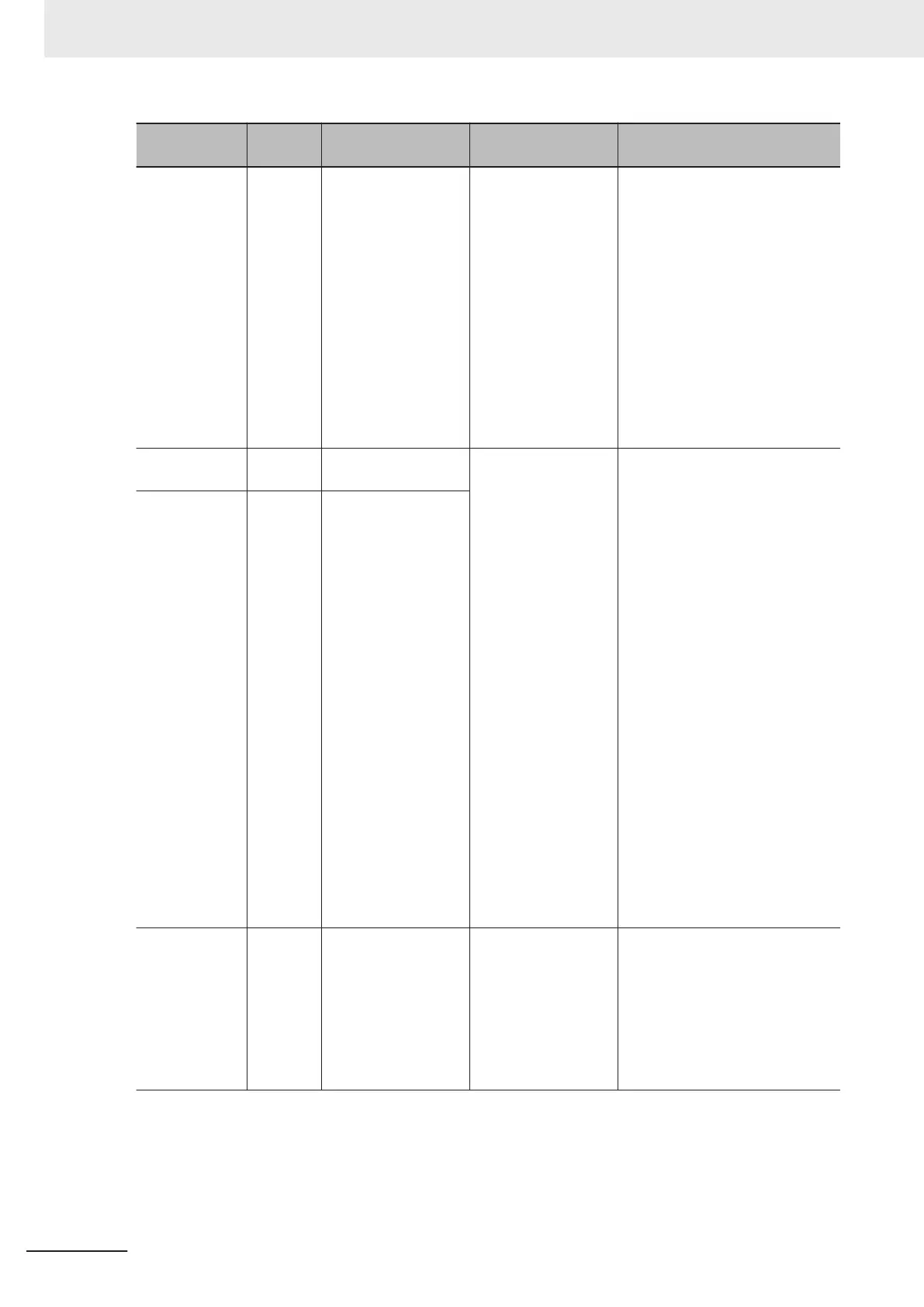
Item No.
Parame-
ter No.
Item Range Display item
3_11 W12
PID Feedback Value
Monitor
-999 to 9990
The PID feedback value is con-
verted using PID Control Maxi-
mum Scale (J106) and PID Con-
trol Minimum Scale (J107) and
displayed.
Display value = (PID feedback
value (%)/100) × (Display maxi-
mum value - Display minimum
value) + Display minimum value
If PID control is disabled, "------”
is displayed.
Even when “----” is displayed for
3_11, W12 displays the input PID
feedback value.
3_12 W13
T
orque Limit Value A
Monitor
-300 to 300 [%]
The selected torque limit set val-
ue of the rated motor torque ratio
is displayed in increments of 1%.
During V/f control, the power run-
ning torque limit is displayed in A
and the regenerative torque limit
is displayed in B.
During vector control and four
quadrants independent (H75 = 0),
the 1st/3rd quadrant torque limit
is displayed in A and the 2nd/4th
quadrant torque limit is displayed
in B. 1st and 3rd, and 2nd and
4th are switched depending on
forward rotation or reverse rota-
tion.
During vector control and four
quadrants identical (H75 = 1), the
same value is displayed in A and
B.
The torque limit is selected by the
torque limit function. (Reference:
6-11 Torque Limit Function on
page 6-
81)
3_13 W14
Torque Limit Value B
Monitor
3_14 W15 Ratio value Monitor 0.00 to 200.0 [%]
A ratio set value of 1.00 time se-
lected via analog input is dis-
played as 100%.
If the ratio set value is not select-
ed, “------” is displayed.
Even when “----” is displayed for
3_14, W15 displays the input ra-
tio set value.
7 Other Functions
7-6
M1 Series Standard Type User's Manual (I669)
 Loading...


