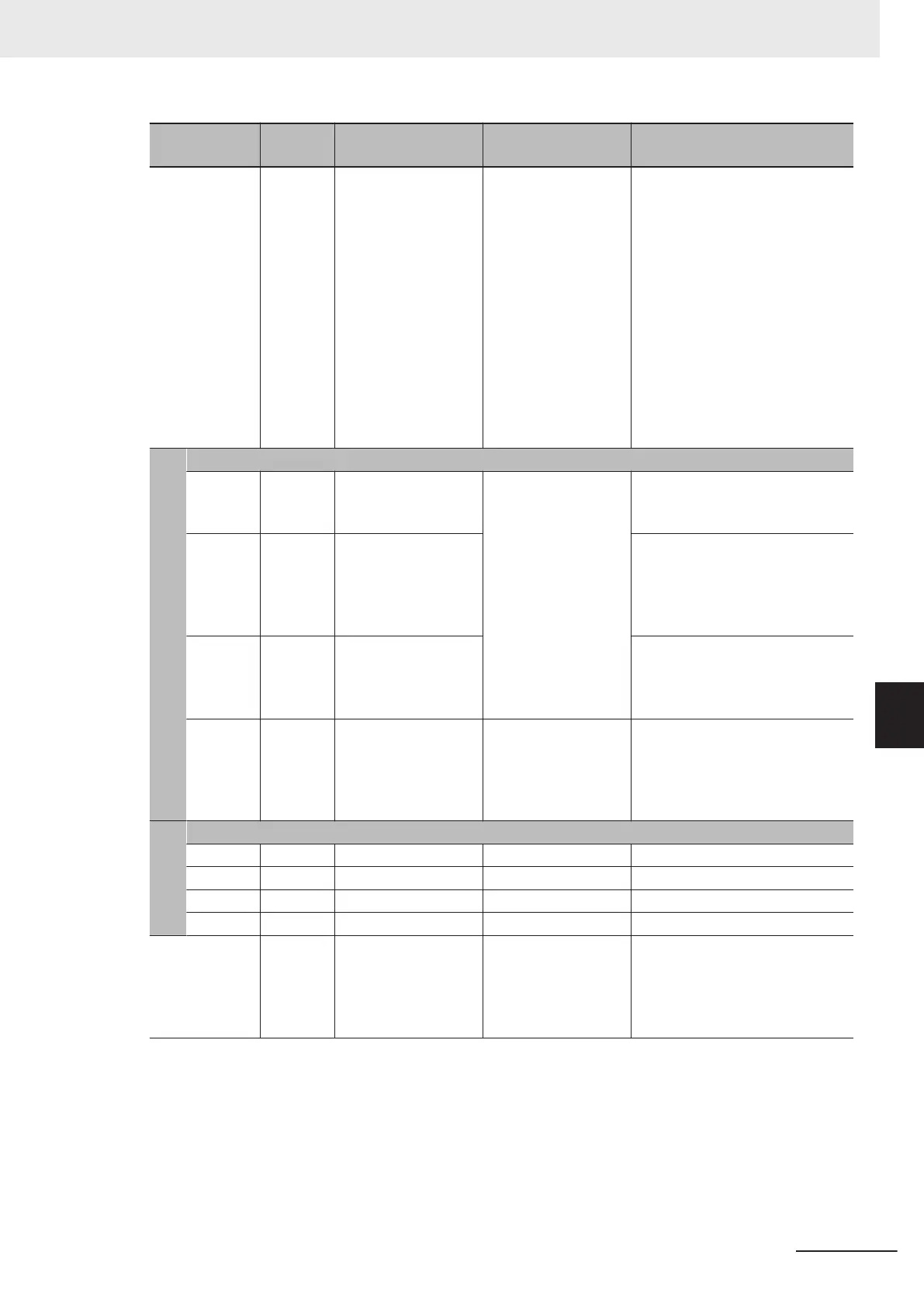
Item No.
Parame-
ter No.
Item Range Display item
3_15 W10 Feed Speed
0.00 to 9999 [m/min]
1000 to 9999 [10 m/
min]
The feed speed is calculated by
multiplying the output frequency
by (1st Frequency Conversion
Coefficient (E50) / Display Coeffi-
cient 1 for T
ransport Time / Auxili-
ary Display Coefficient 1 for
Speed Monitor (E39)) and dis-
played.
Feed speed = Output frequency ×
(E50 / E39)
If the display value is 10000 or
above, the x10 LED lights up and
the value of display value/10 is
displayed.
When position control is enabled (When DI terminal SPD is not allocated)
3_17
W144,
W145
Target Position Moni-
tor (MSB), Target Po-
sition Monitor (LSB)
F000 0000 hex to
0FFF FFFF hex
(Hexadecimal)
(Equivalent to
-268435456 to
268435455)
The target position user value
(hexadecimal) is displayed alter-
nately in upper bytes/lower bytes.
3_18
W142,
W143
Feedback Current
Position Monitor
(MSB), Feedback
Current Position
Monitor (LSB)
The current position is displayed
alternately in upper bytes/lower
bytes.
3_19
W146,
W147
Position Deviation
Monitor (MSB), Posi-
tion Deviation Moni-
tor (LSB)
The position deviation is dis-
played alternately in upper bytes/
lower bytes.
3_20 W152
Touch Probe Status
0000 hex to FFFF
hex (Hexadecimal)
bit 0: Touch probe 1 Enb
bit 1: T
ouch probe 1 PLc
bit 8: T
ouch probe 2 Enb
bit 9: T
ouch probe 2 PLc
Other than the above: Reserved
When position control is enabled (When DI terminal SPD is allocated)
3_17 - Reserved - -
3_18 - Reserved - -
3_19 - Reserved - -
3_20 - Reserved - -
3_21 W32 PID Output Monitor
-150 to -99.9, 9.99 to
99.99, 100.0 to 150.0
[%]
The PID output value is displayed
in increments of 0.01%. (The
maximum frequency is 100%.)
If PID control is disabled, “----” is
displayed. 0 is displayed in W32.
7 Other Functions
7-7
M1 Series Standard Type User's Manual (I669)
7-1 Status Monitors
7
7-1-1 Operation Monitor
 Loading...