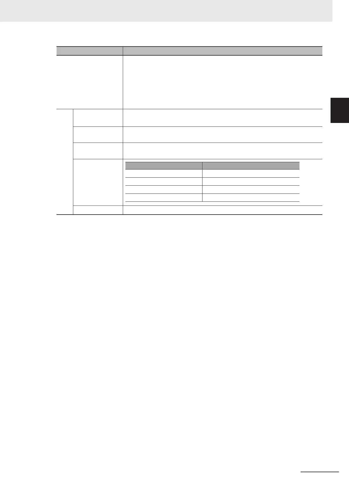
Item Specifications
Other functions AVR function, V/f characteristics switching, Upper/Lower limit, Multi-step speed (16
steps), Starting frequency adjustment, Jogging operation, Carrier frequency adjust-
ment, PID control, Frequency jump, Analog gain/bias adjustment, S-shape acceler-
ation/deceleration, Electronic thermal characteristics/ level adjustment, Restart
function, Torque boost function, Fault monitor, Soft lock function, Frequency con-
version display
, USP function, 2nd control function, UP/DOWN, Overcurrent sup-
pression function, etc.
Gen-
eral
spec
ifica-
tions
Operating ambient
temperature
*6
-10 to 50°C (Derating required)
Storage ambient
temperature
-25 to 70°C (Short-time temperature during shipment)
Operating ambient
humidity
5% to 95% (with no condensation)
Vibration resist-
ance
Vibration Frequency
2 to less than 9Hz
9 to less than 20Hz
20 to less than 55Hz
55 to less than 200Hz
3mm (0.12inch) (Max. amplitude)
1
G
0.2G
0.1G
Specification
Location At a maximum altitude of 1,000 m, indoors (without corrosive gases or dust)
*1. The enclosure rating complies with JISC0920.
*2. If you must use the motor at higher than 50/60 Hz, check the allowable maximum motor speed and other
information with the motor manufacturer.
*3. In the HND/ND (light load) mode or PM motor mode compared with the HHD/HD (heavy load) mode, for
some parameters, the default data and setting range also dif
fer. For details, refer to 5-2-2 Load Mode Selec-
tion on page 5-12.
*4. By default, the maximum frequency is adjusted to 10 V for a voltage input of 0 to 10 VDC and to 20 mA for a
current input of 4 to 20 mA, respectively. If necessary, adjust the default parameter settings. For details, re-
fer to 7-3-2 Analog Input Adjustment Function on page 7-38.
*5. The analog output shows values that can only be used as a guide for analog meter connection. The maxi-
mum output value may differ from 10 V or 20 mA due to the variability of the analog output circuit. If neces-
sary, adjust the default parameter settings.
*6. Derating of the rated output current of the inverter may be required depending on the heavy/light load mode
selection, operating ambient temperature, side-by-side installation, and carrier frequency settings.
Use the inverter in an appropriate environment according to A-1 Derating Table on page A-2.
1 Overview
1-17
M1 Series Standard Type User's Manual (I669)
1-3 Specifications
1
1-3-1 Standard Specifications

 Loading...


