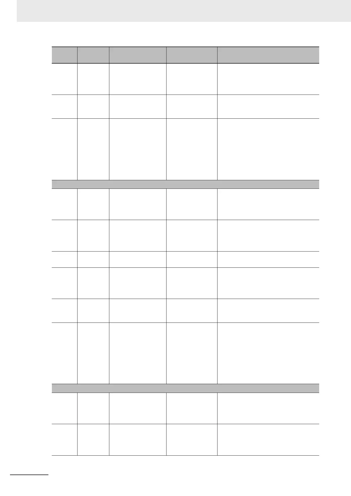
Item
No.
Parameter
No.
Item Range Description
6_07 Z56
Third Last Alarm Info.
Cumulative Ope.
Time
0 to 655,350 hours
The number of operations of the motor
(number of times the RUN command for
the inverter is turned ON) is calculated
and displayed.
6_09 Z58
Third Last Alarm Info.
Main Circuit DC Volt-
age
0.0 to 999.0 [V]
The Main Circuit DC Voltage of the inver-
ter is displayed.
6_30
X138
Third last Alarm Info.
Cumulative Running
Time
0 to 655,350 hours
The cumulative time of the inverter RUN
state is displayed.
The cumulative operation time is dis-
played alternately in the upper digits and
lower digits.
When the lower three digits are dis-
played, an h (hours) is displayed in the
lowermost digit.
5 Fourth last alarm
6_00 X141
Fourth last Alarm Info.
Output Frequency
0.00 to 99.99,
100.0 to 590.0 [Hz]
The output frequency before slip com-
pensation is displayed in increments of
0.01 Hz. A value of 100.0 Hz or higher is
displayed in increments of 0.1 Hz.
6_01
X142
Fourth last Alarm Info.
Output Current
0.00 to 99.99,
100.0 to 655.3 [A]
The output current is displayed. A cur-
rent value of 100.0A or higher is dis-
played in increments of 0.1 A.
Display unit: A (Ampere)
6_06 X149
Fourth Last Alarm In-
fo. Running Status
0000Hex to
FFFFHex
The operation status is displayed by a
four-digit hexadecimal.
6_07 X143
Fourth Last Alarm In-
fo. Cumulative Ope.
time
0 to 655,350 hours
The number of operations of the motor
(number of times the RUN command for
the inverter is turned ON) is calculated
and displayed.
6_09 X144
Fourth Last Alarm In-
fo. Main Circuit DC
V
oltage
0.0 to 999.0 [V]
The Main Circuit DC Voltage of the inver-
ter is displayed.
6_30
X148
Fourth Last Alarm In-
fo. Cumulative Run-
ning Time
0 to 655,350 hours
The cumulative time of the inverter RUN
state is displayed.
The cumulative operation time is dis-
played alternately in the upper digits and
lower digits.
When the lower three digits are dis-
played, an h (hours) is displayed in the
lowermost digit.
6 Fifth last alarm
6_00 X151
Fifth Last Alarm Info.
Output Frequency
0.00 to 99.99,
100.0 to 590.0 [Hz]
The output frequency before slip com-
pensation is displayed in increments of
0.01 Hz. A value of 100.0 Hz or higher is
displayed in increments of 0.1 Hz.
6_01
X152
Fifth Last Alarm Info.
Output Current
0.00 to 99.99,
100.0 to 655.3 [A]
The output current is displayed. A cur-
rent value of 100.0A or higher is dis-
played in increments of 0.1 A.
Display unit: A (Ampere)
7 Other Functions
7-24
M1 Series Standard Type User's Manual (I669)

 Loading...


